Low-Cost STM32 Development Board
I am using STM32 microcontrollers more and more for work and personal project, and couldn’t find an off-the-shelf development board that satisfied the following requirements:
- STM32 MCU
- under £10 each (ideally closer to £5)
- simple schematic
- easy mounting holes
- CAN bus compatible, with onboard transceiver
- USB-C
- CAN bus and USB concurrently
- flat bottom / single sided
- easy to manufacture (e.g. PCBWay / JLCPCB PCBA)
When talking to someone about another recent PCB I’d made (a USB slider with a SAMD21), the STM32F072 came up. I looked through the datasheet and saw that it had USB and CAN, and unlike a lot of the smaller/lower cost STM32s, they were on separate pins! This means I can use it as a general purpose board for reading and writing CAN bus messages over USB.
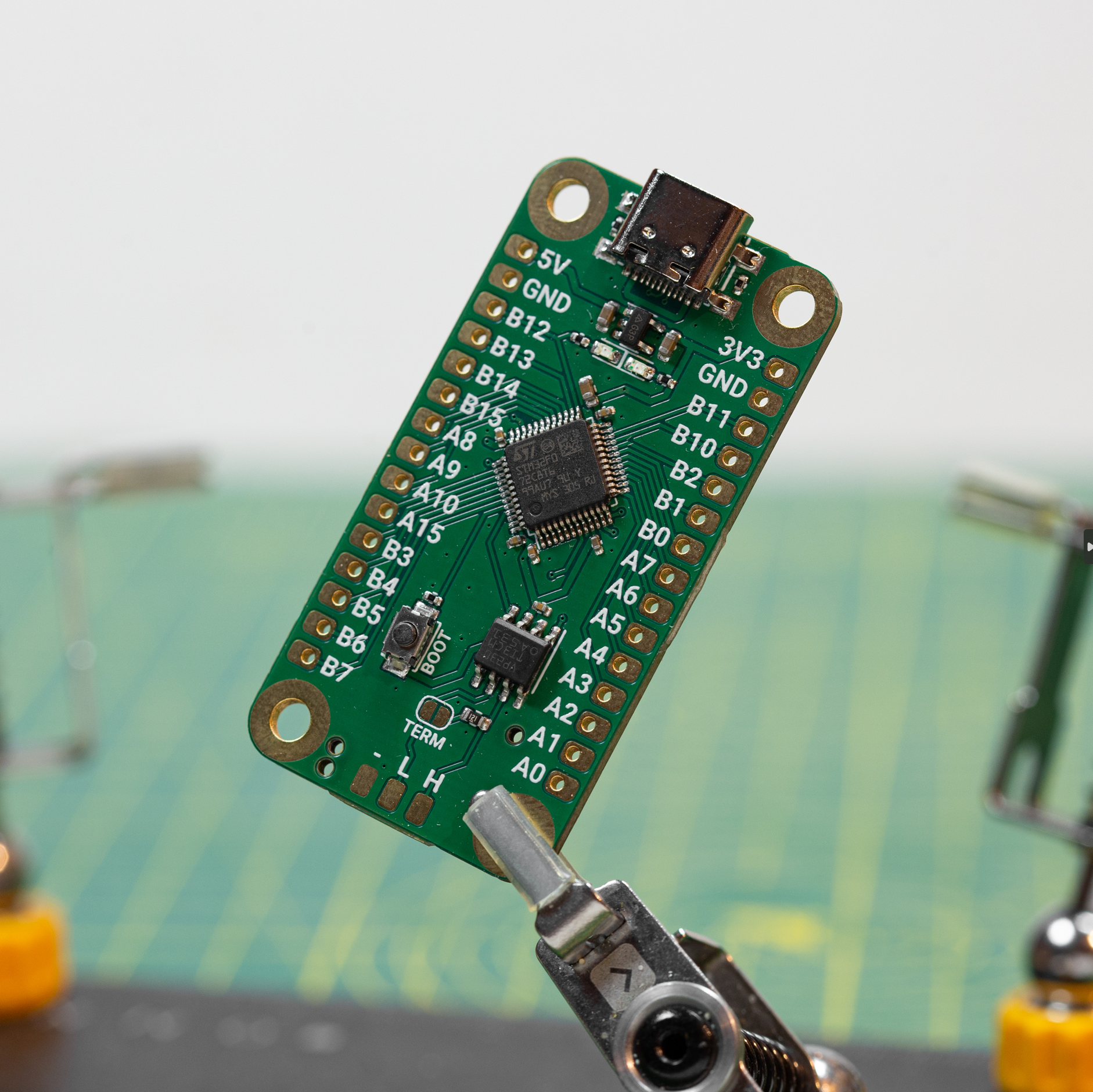
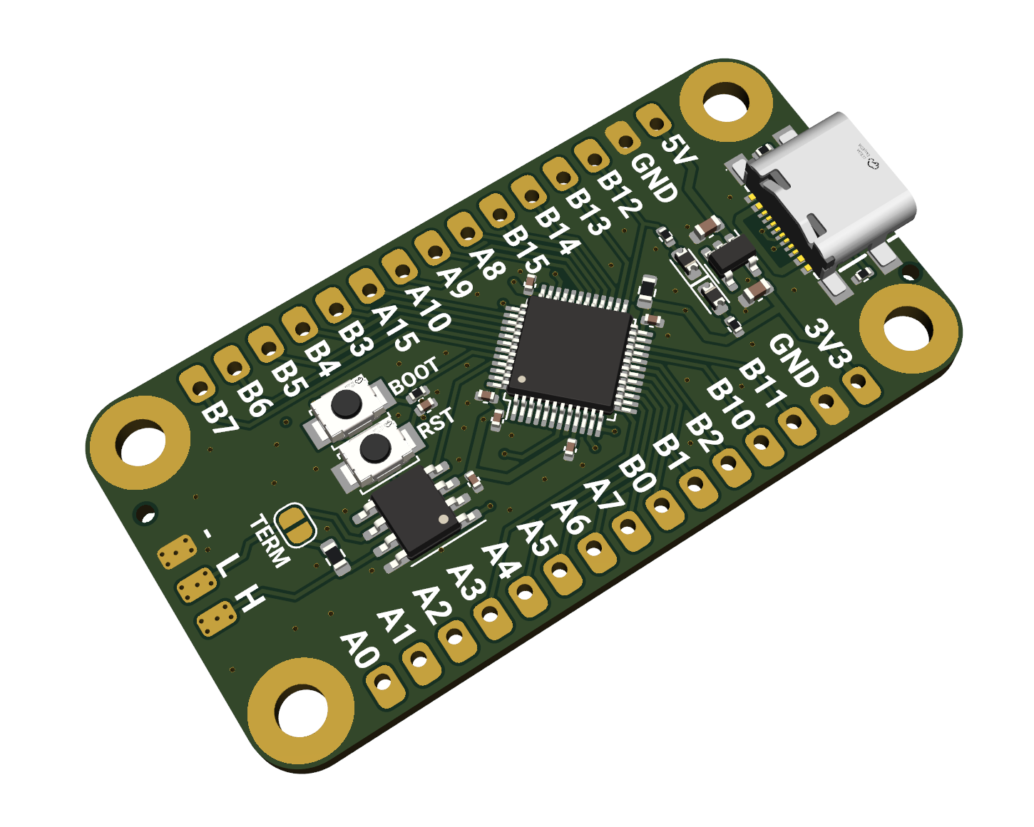
I designed a simple development board, with two rows of GPIO, a boot button for STM32 DFU mode (for programming), USB-C with CC resistors, a 5V to 3.3V regulator, a CAN bus transceiver (with pads and termination resistor jumper), and SWD programming pads on the rear. Although not ideal for all applications, USB and CAN on this STM32F072 can also work crystal-less, so there is no additional external clock - this reduces cost and complexity.
Although I used standard 2.54mm spacing for the pin headers, the PCB and mounting holes are all metric. Many development boards from companies like Adafruit are designed in the USA, they instead use imperial sizes for the PCB outline and moutning holes. Not a huge issue, but it’s nice to not need to use inches when mounting this to things.

20 of these boards manufactured and assembled by JLCPCB comes to $85.29, including shipping. That’s about £3.30 per board. Super cheap!
Although the board functions with no issues, I did start to run into speed/memory limitations sooner than I would have liked. For simple or low power requirements, it’d be perfect and it’s hard to argue with the price. However, I decided to swap the F072 for a L433, which (seems!) pin-compatible with the F072, but has about 2x the clock speed, and 4x the memory. I also added a reset button, as having to unplug USB to power-cycle to enter DFU mode got annoying pretty quickly! I also broke out USB pads underneath the USB-C port, as sometimes I mount PCBs in locations where the USB port isn’t easily accessible, or I need a different connector.

Annoyingly, although the F072 and L433 are similarly priced on Mouser/Digikey, the L433 is a lot more expensive on JLCPCB (I assume as it’s less popular, so lower stock). This does mean the newer version will cost more, but it should still work out to around £5 per board at quantities of 20+.
Usage
I’ve been using these boards with the stm32duino core for Arduino. Either using the Arduino IDE (following these steps), or PlatformIO within VSCode. Although nothing is stopping usage with other STM32 tools/IDEs.
Arduino IDE settings
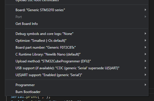
See the below screenshot for Arduino IDE settings, first selecting the board (Generic STM32F0 or STM32L4 series) followed by the board part number (Generic F072C8Tx or L433CCTx), upload method (DFU for USB, or SWD for the SWD pads on the back, if using an external programmer) Generic Serial and CDC USB can then be selected to use serial monitor over USB.

To put the board into DFU mode to program over USB, hold down the boot button, and either press the reset button, or unplug and plug back in the USB if there isn’t a reset button. No COM port will show up when in DFU mode, but it will show up in Device Manager (Windows). Once programmed, a COM port will become available for the serial connection (assuning the above settings are selected).
The user LED is on pin PB12, and CAN RX and TX are on PB8 and PB9.
Example Code
// Serial and LED code for Jordan's STM32 Dev Boards

void setup() {
  Serial.begin(115200);
  pinMode(PB12, OUTPUT);
}

void loop() {
  digitalWrite(PB12, HIGH);
  Serial.println("LED ON");
  delay(1000);

  digitalWrite(PB12, LOW);
  Serial.println("LED OFF");
  delay(1000);
}