Pseudo Large Format Digital Camera
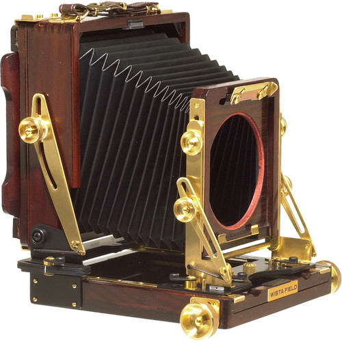
Large format cameras are ones which are designed to photograph a much larger image than ‘standard’ cameras. The majority of large format cameras are similar to that shown below, which takes a 4x5 (inch) photo using photographic film. The main reason to use a large format camera is to get a higher resolution than standard sized formats. As high resolution digital photography using smaller sensors has become more popular, large format film cameras have fallen in popularity.
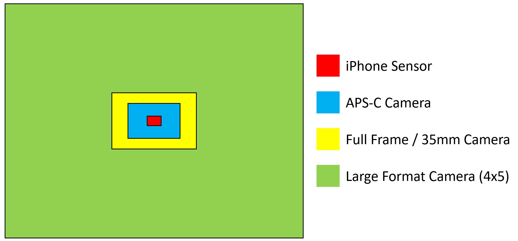
Below is a comparison of a large format camera frame, compared to the sensor size of an iPhone, an APS-C sensor which is a common size for most DSLRs, and a full-frame sensor which is used for professional cameras and is equivalent to standard 35mm photography film in size. It can be seen that all of these other film/sensor sizes are dwarfed by that of large format!
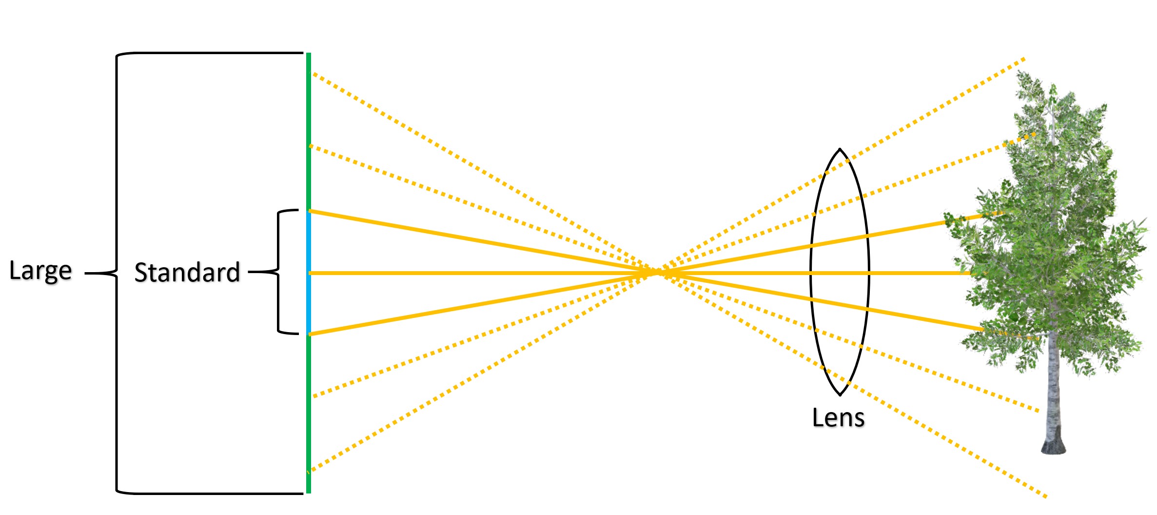
Old large format lenses can be easily found on sites like eBay for relatively little money, and although using them on a standard digital camera is possible, only the centre of the frame is captured. This is because they are designed for a much larger film/sensor size. From the illustration below, it can be seen that when a large format lens is mounted in front of a standard sized sensor, it can only see a small part of the full image. This reduction in view is commonly known as the ‘crop factor’.
In order to produce an image which covers the entire 4x5 frame, instead of rigidly mounting the lens to the camera body, the camera body can be translated around the 2D plane of the sensor behind the lens. Individual images can then be captured and stitched together using a PC to create a single high-resolution image showing the full 4x5 frame projected by the large format lens.
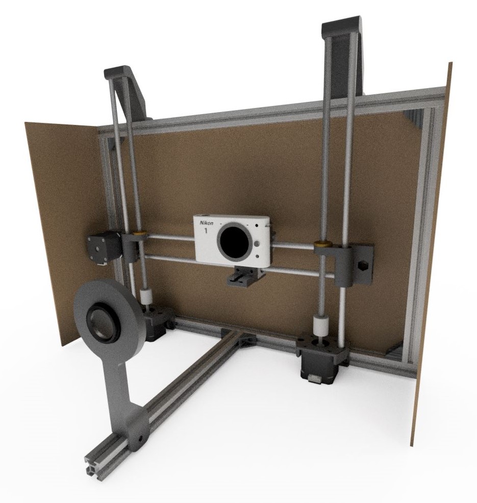
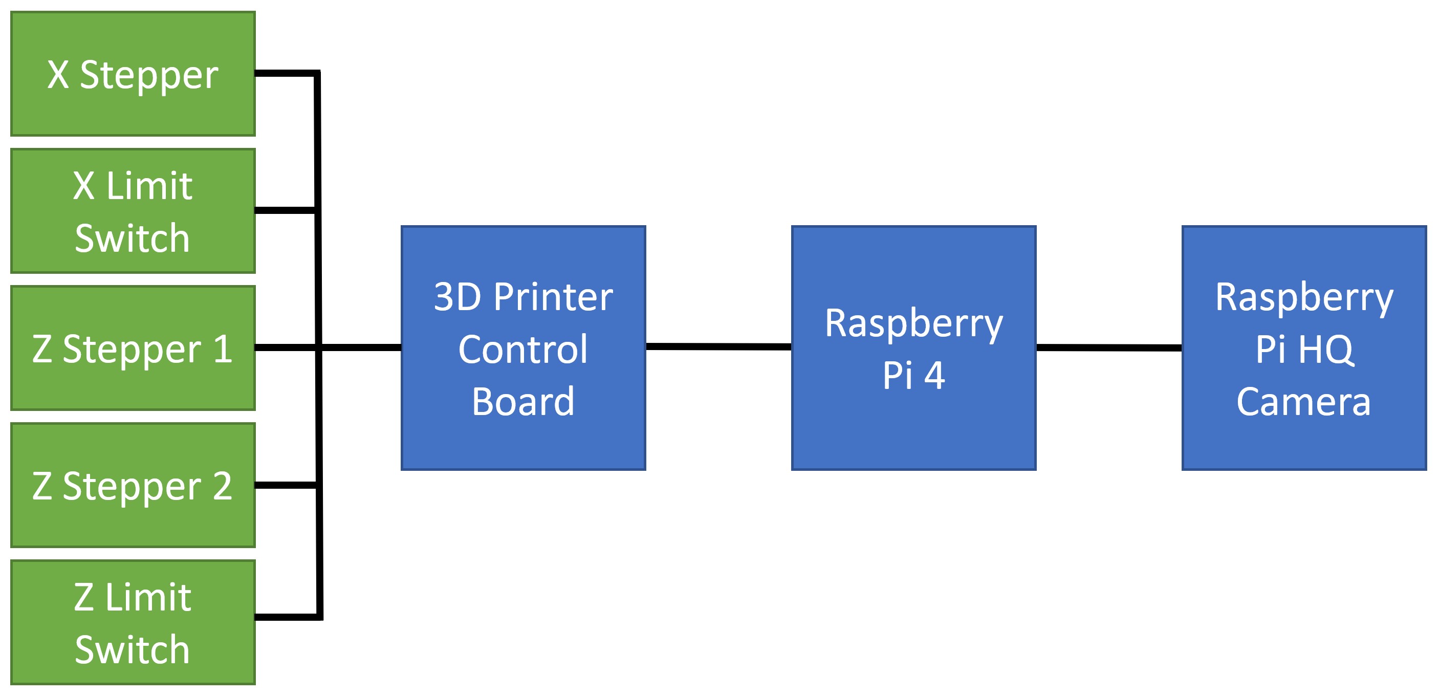
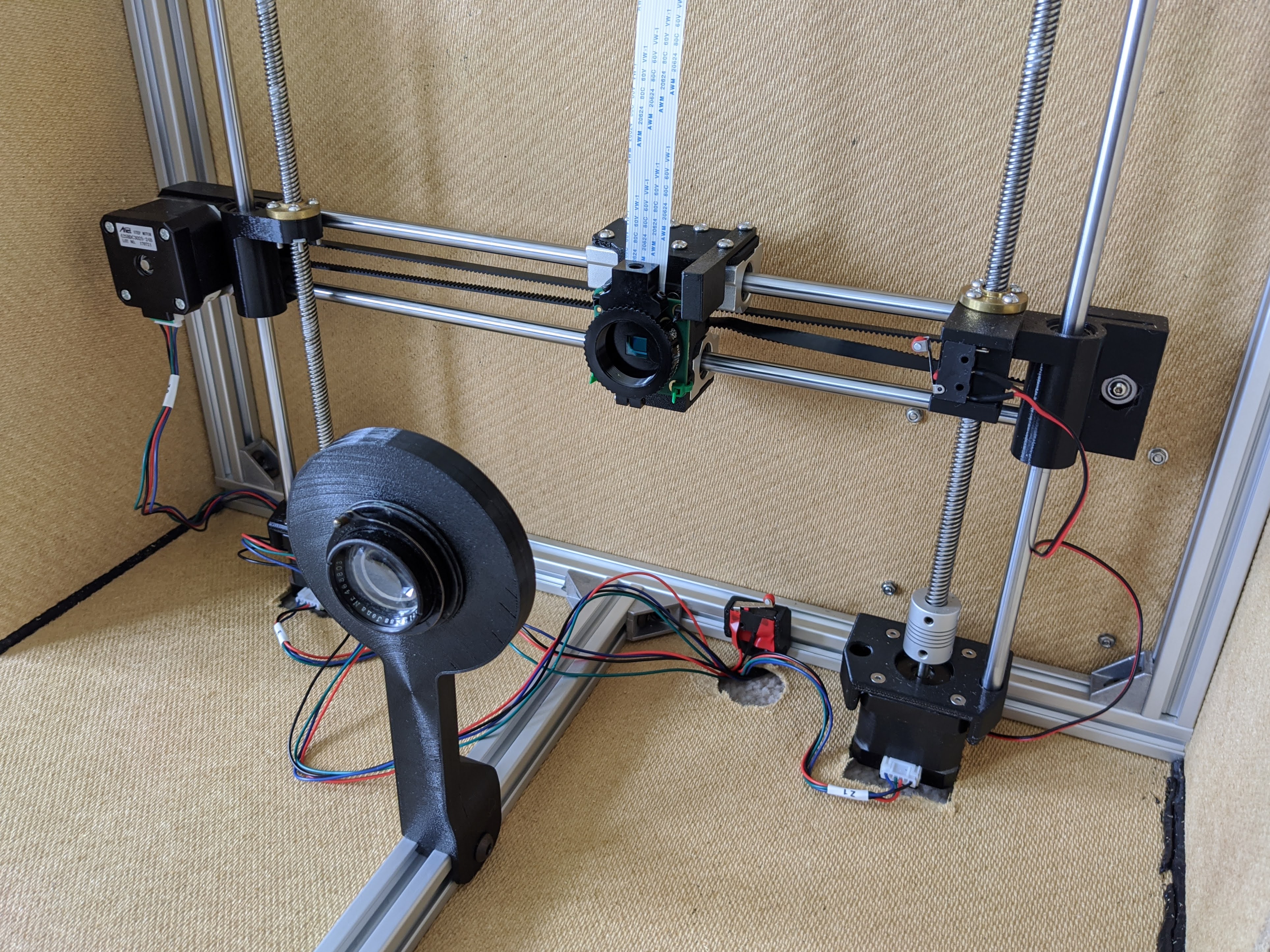
To move the camera around on a fixed plane, a similar motion mechanism to a 3D printer was used. The frame is constructed using 2020 aluminium extrusion, with the camera mounted to bearings which run on smooth rods. The camera is pulled left and right using a belt connected to a stepper motor. This horizontal axis is mounted at each end to a threaded rod, which raises and lowers the camera using two more stepper motors. The lens is mounted to a rail which allows it to slide backwards and forwards in order to focus. Rigid board is mounted to the back and sides of the frame to block excess light. The motion system is controlled using a 3D printer control board, with a custom program written using the Arduino IDE.
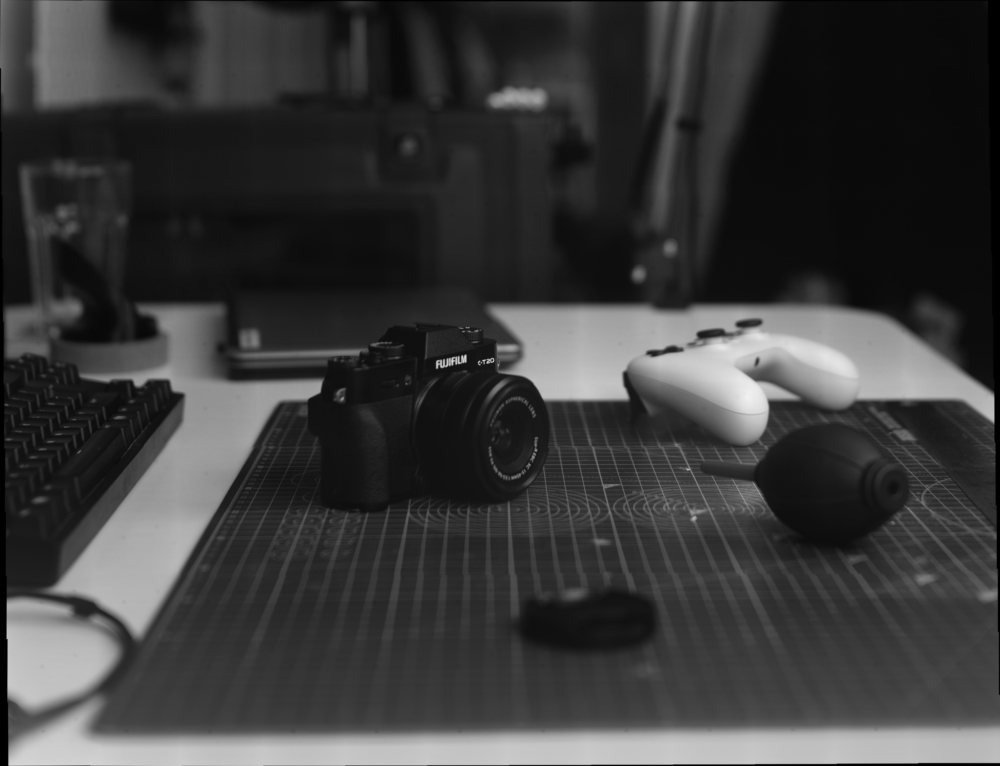
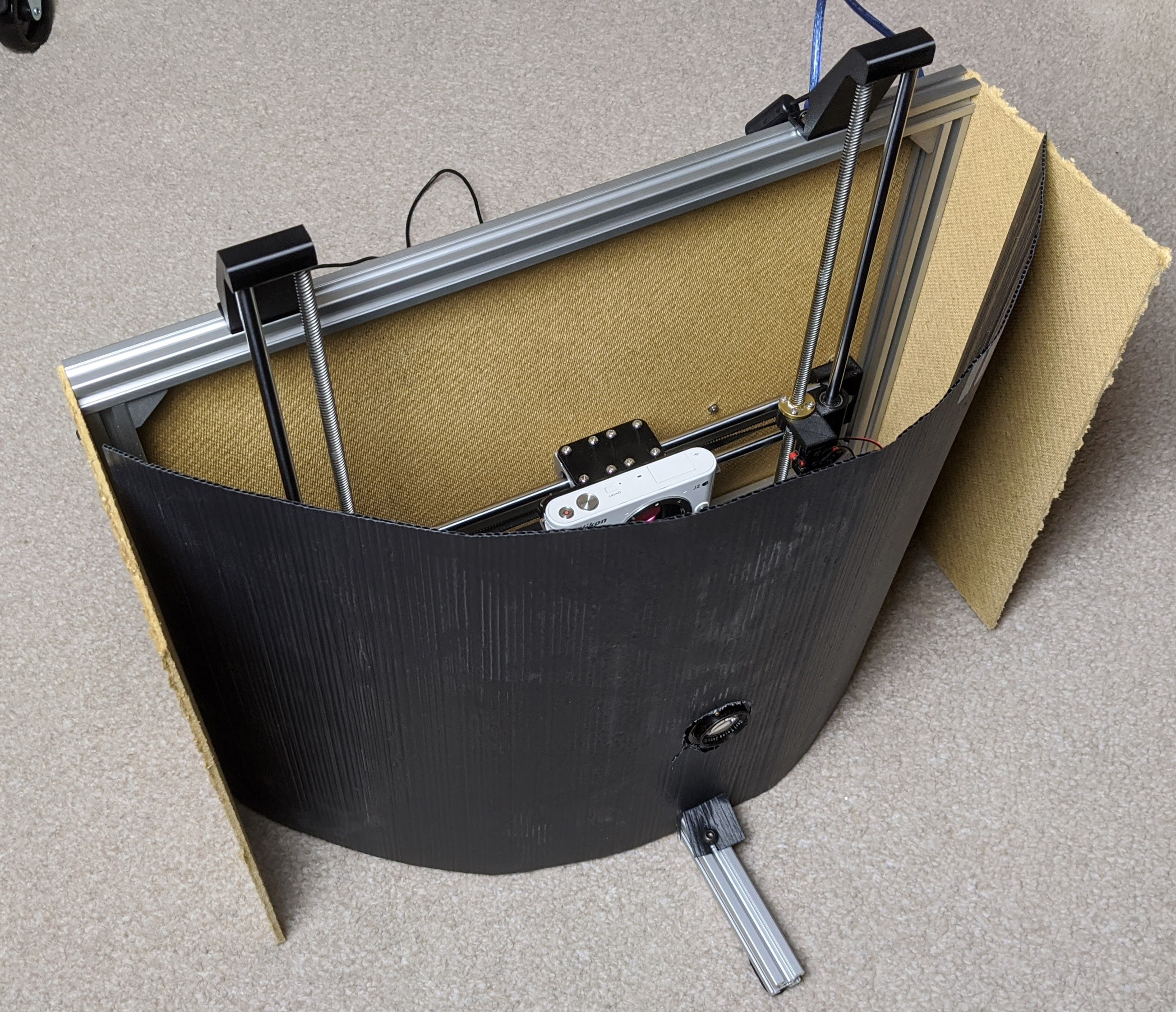
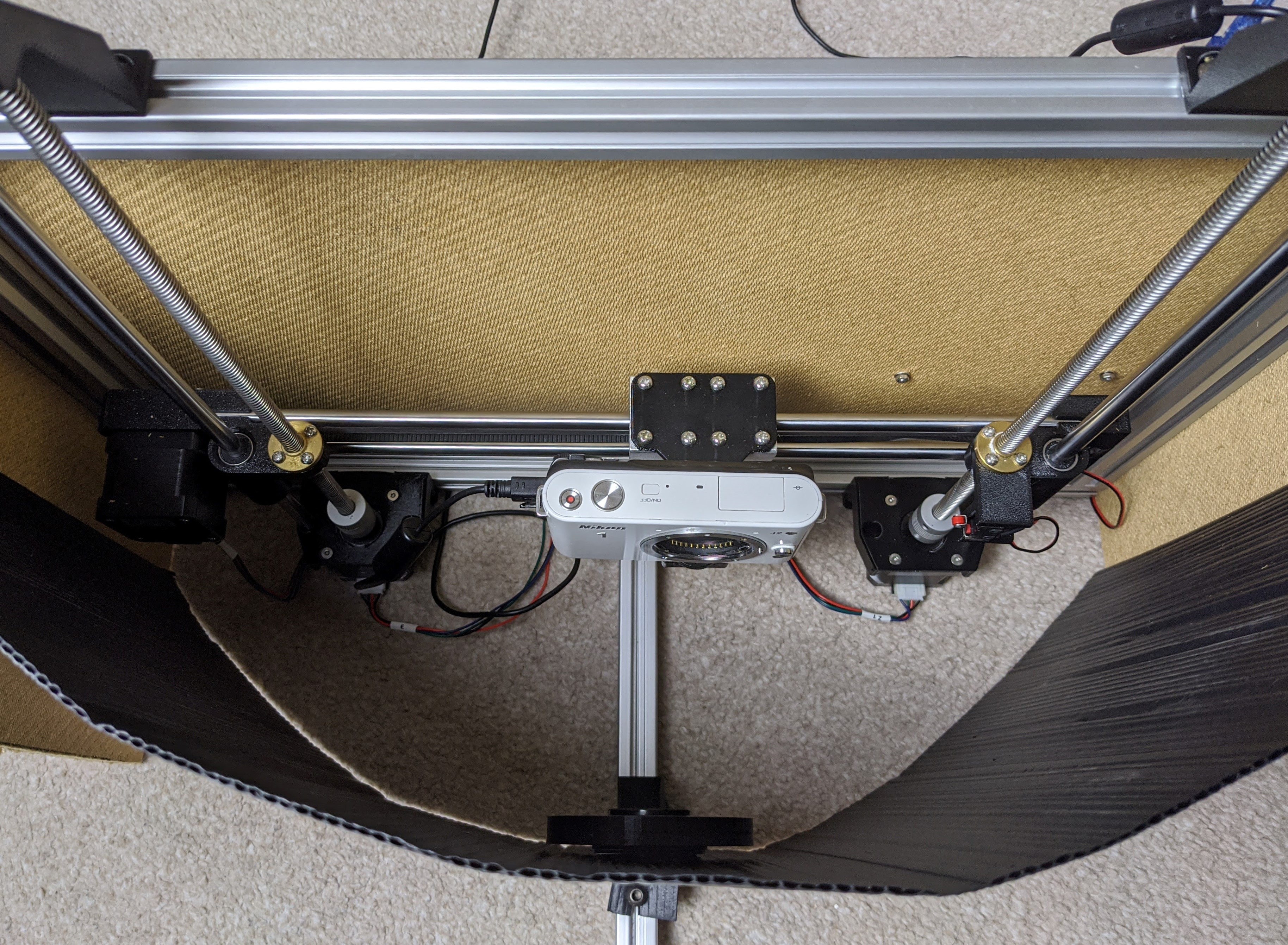
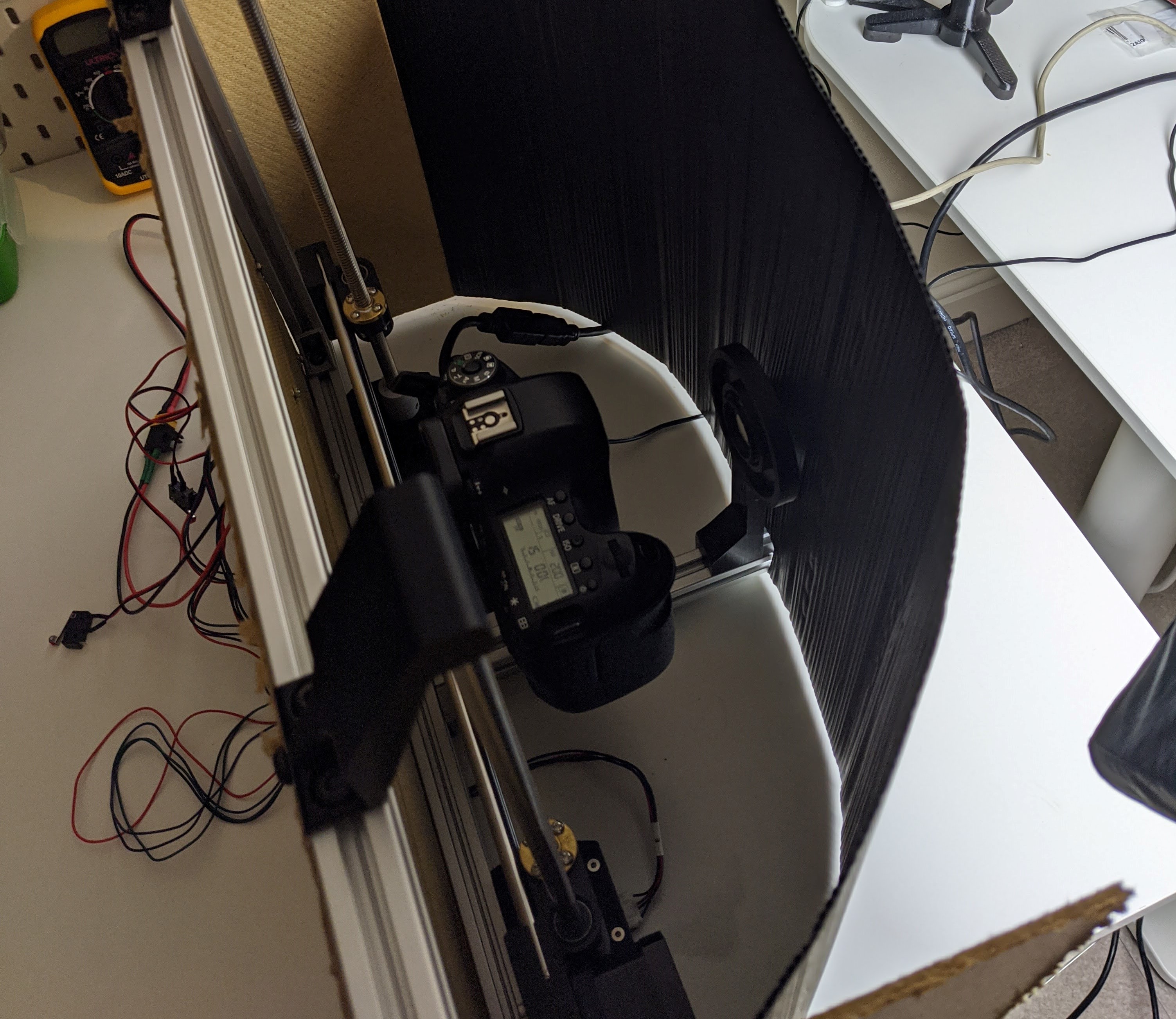
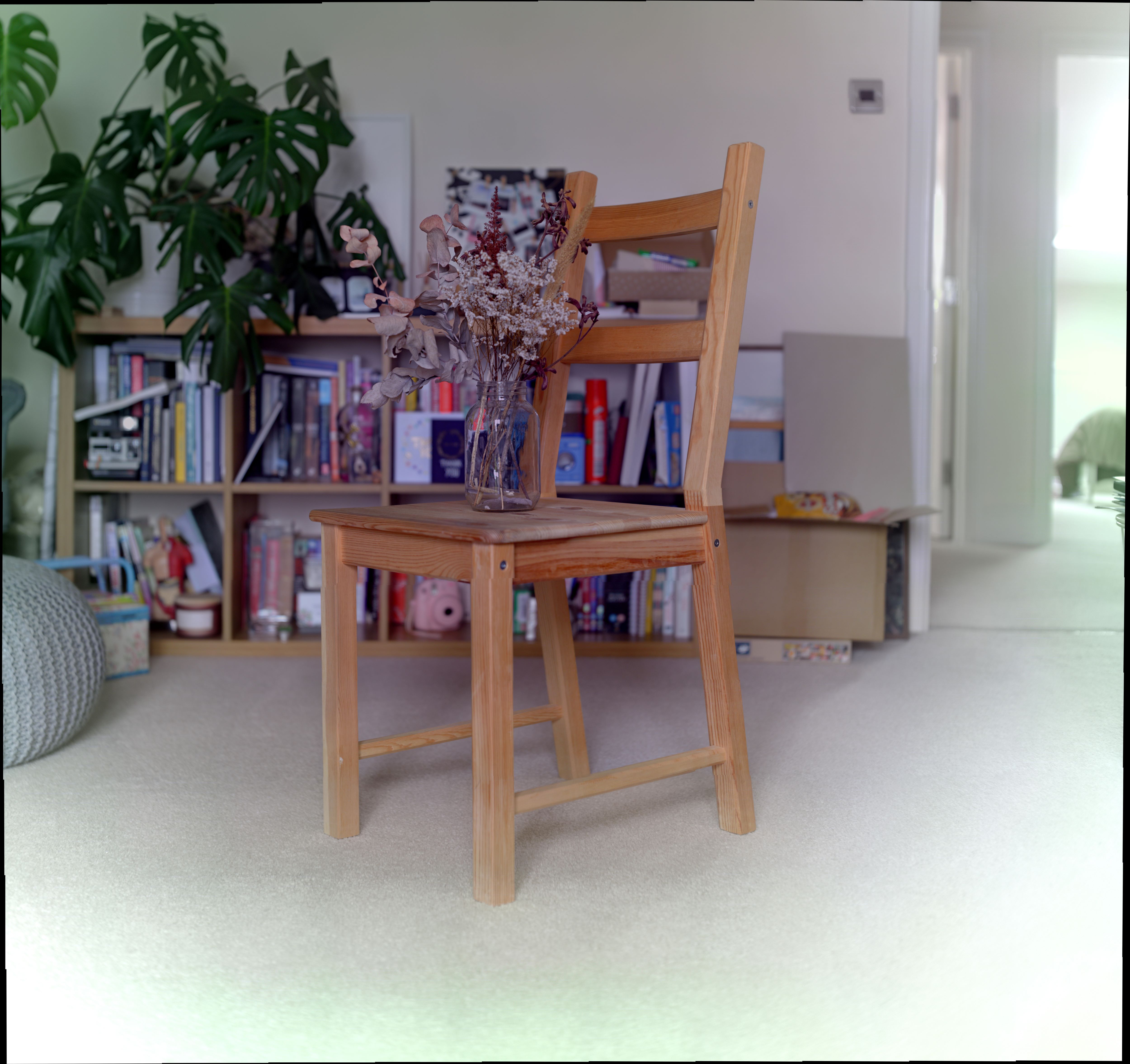
Below are a few images of the initial camera setup. The rigid back and side panels can be seen, along with a flexible black front piece. Another black piece is placed on top when the camera is in use to block more excess light from entering. In an ideal world the camera rig would be completely light sealed aside from the lens - this will be done once the camera rig is fully functional. A Raspberry Pi is mounted to the back board which controls the camera and sends commands to the 3D printer control board below it.
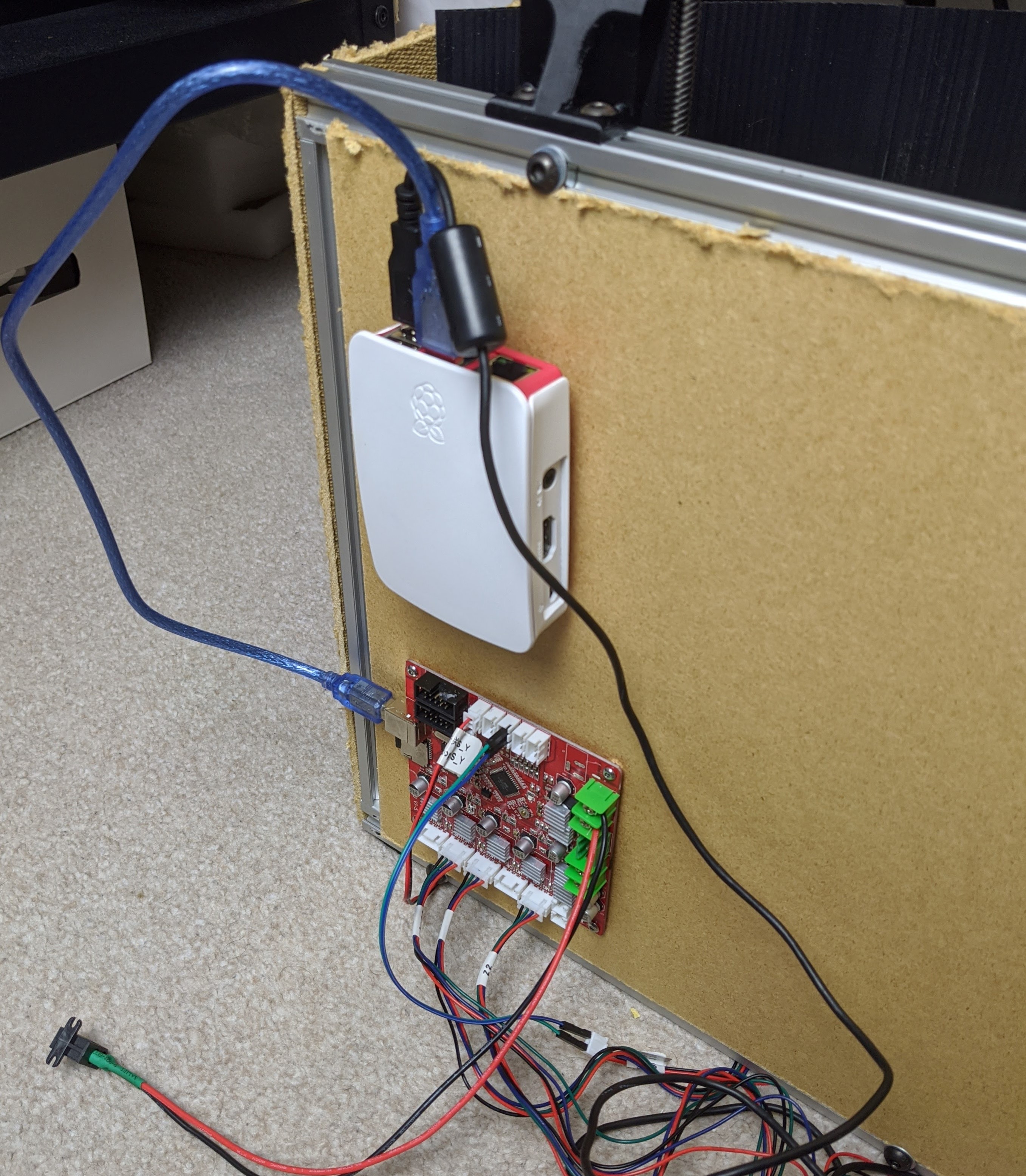
As stepper motors do not have any built-in position sensing, two switches were added which allows the system to find a ‘home’ position as a point of reference. The stepper motors are then calibrated and so can move from this home position to wherever the program commands.
Stepper motors are connected to the old 3D printer control board, and a basic program was created using the Arduino IDE which takes commands from the Raspberry Pi. These commands tell the control board what direction to turn the stepper motors, and how many steps to move by. There is also a ‘home’ command which runs at the start of the program to position the camera in a known location - using a limit switch on each axis.
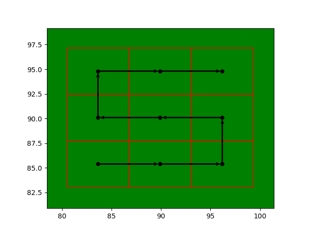
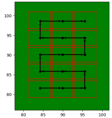
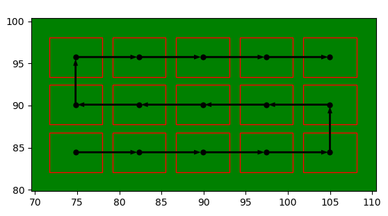
Python is used on the Raspberry Pi to plan a route for the motion system to take. The user inputs the number of desired rows and columns which the final image will be made up of, and the starting position and path is generated. This path is centred behind the lens, in the middle of the known limits of the motion system. The path and individual image locations are then plotted. This path planner also has an input for image overlap - which is useful both for blending the images later, or producing a coarse test path.
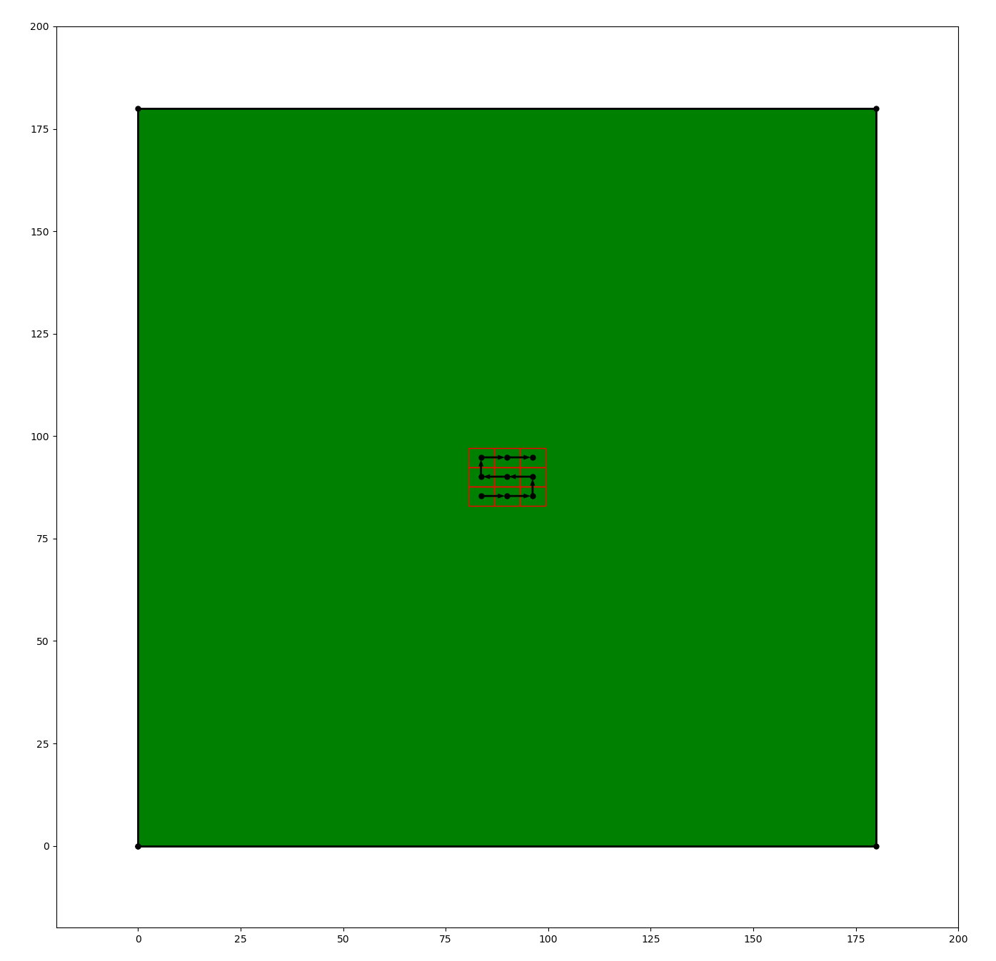
Once the path is confirmed, the Raspberry Pi sends each movement command to the motor control board, stopping to take an image at each pre-generated location.
Test 1: Using a Canon 6D
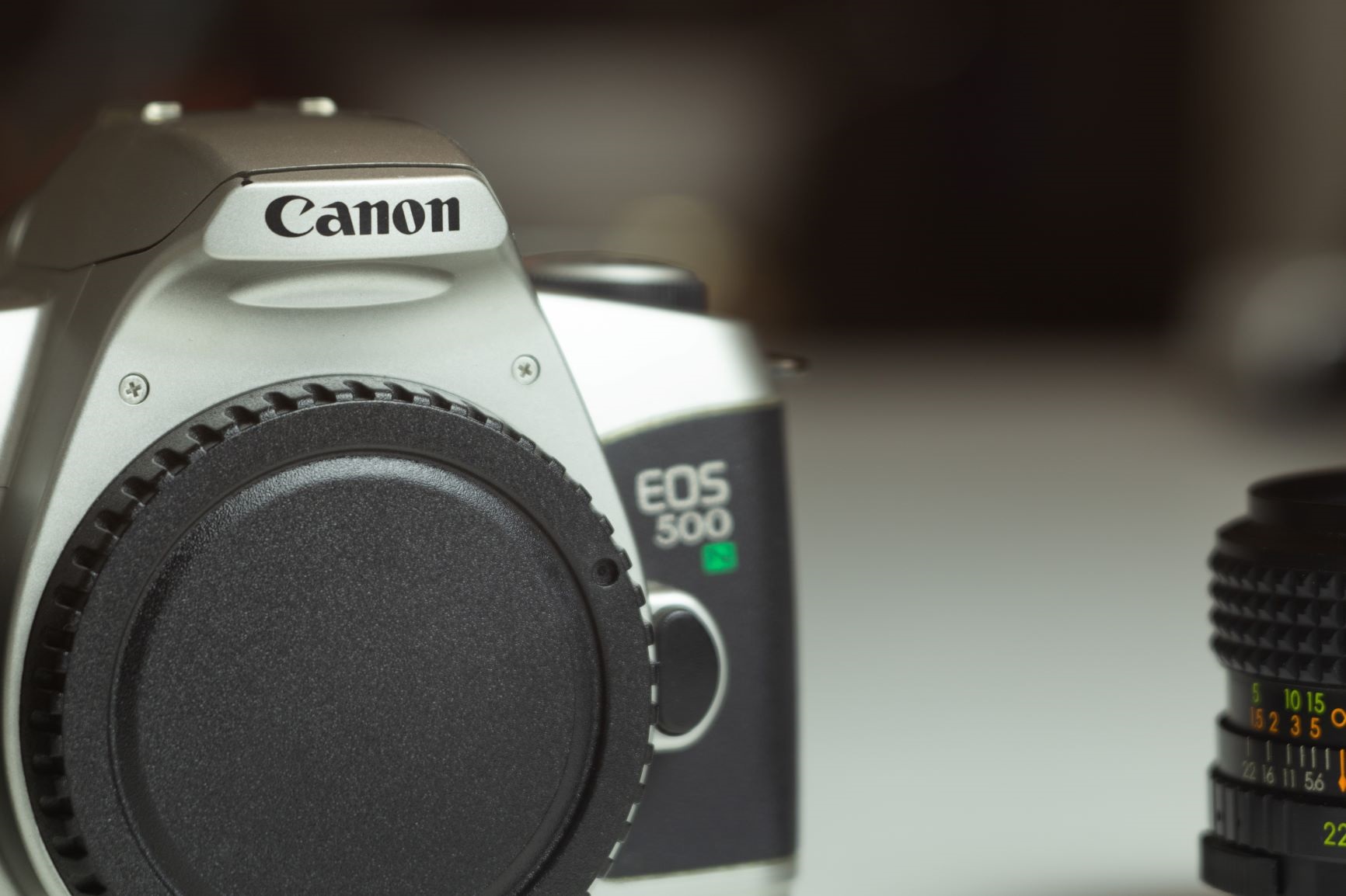
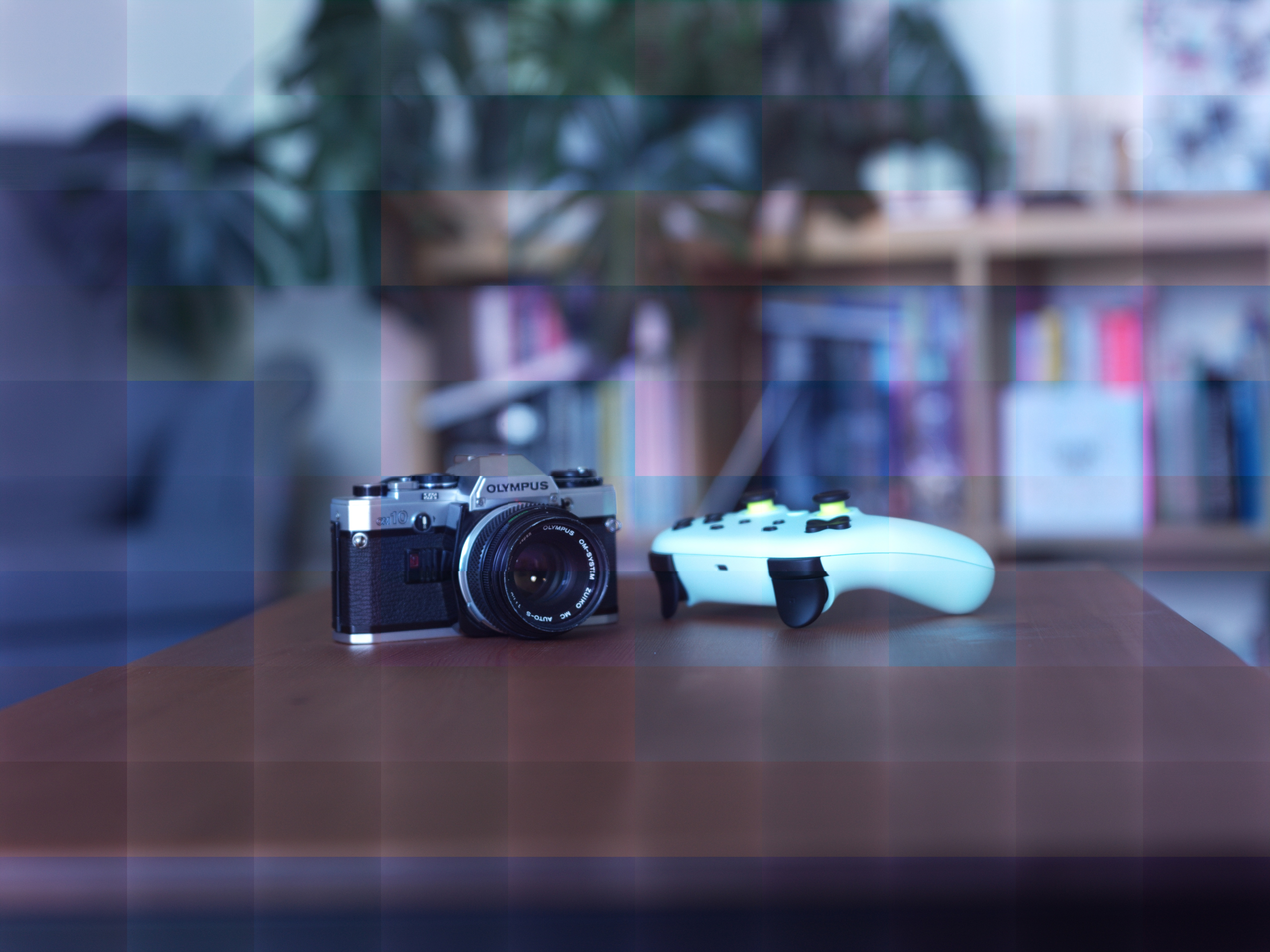
Below is a single frame taken with the camera. As expected, the image is quite zoomed in, as it is only seeing a small frame from the middle of what the full lens is projecting.
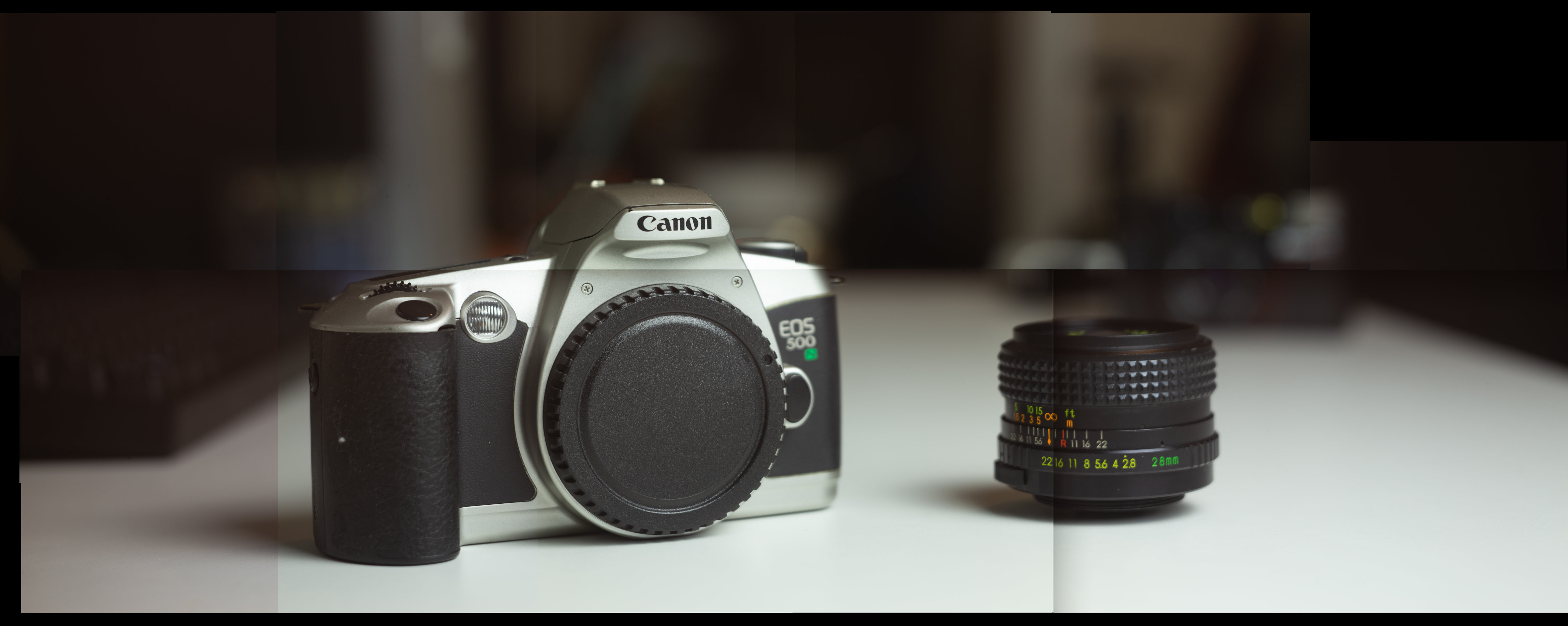
A larger image was then created using a series of individual images, taken by moving the camera around slightly. The images were merged in Photoshop. It can be seen that there are slight differences between individual images, making it easy to spot where one stops and the next one starts.
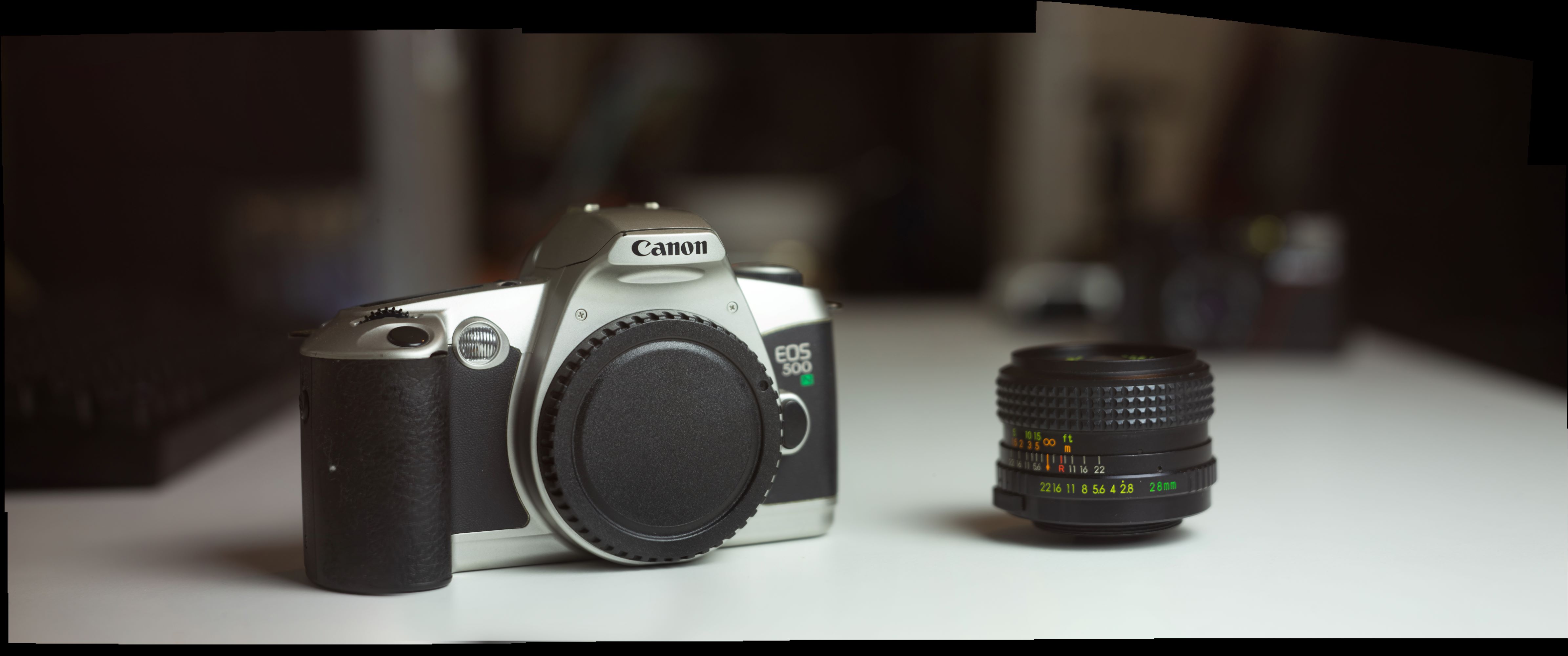
Photoshop has an option to blend the images and correct for vignetting, which does a good job at eliminating the visible individual image edges. The resolution of this image is 16507x6906 (approximately 114 megapixels).
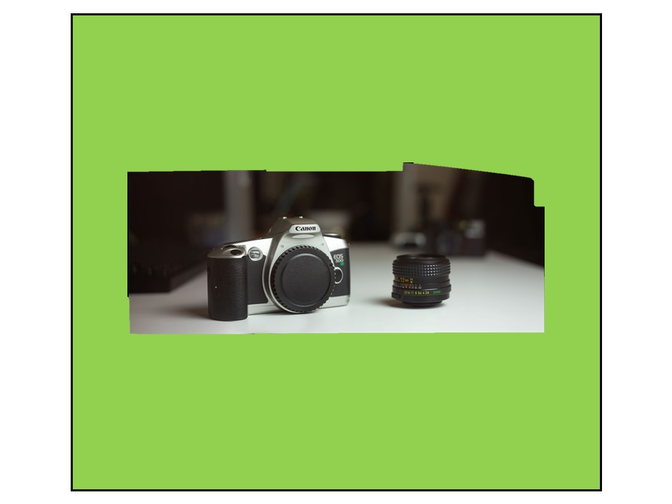
The above test images are only taken from a small section of the overal large format lens projection (see below for an approximation).
Test 2: Nikon 1 J2
Although the Canon 6D performed well, further testing will be done using a Nikon 1 J2. Compared to the Canon, this Nikon has a smaller sensor but a higher pixel density. This means that more individual images will need to be taken to produce the same field of view, but the final resolution will be higher. I will also be switching from using Photoshop to merge the images, to using Microsoft Image Composite Editor (MS ICE). Below is the a series of images taken using the Nikon, aligned but pre-stitching. The overall image is visable, but there are some initially strange artifacts to the right of the image. As the camera sensor is recessed into the body of the camera, as it moves to the side, the body begins to obstruct the sensor’s view of the lens. This causes part of that individual image frame to contain a black bar on one side.
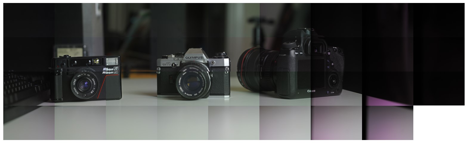
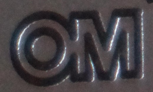
There is also a pink shift to the individual images on the right. This is due to a colour shift in a protective layer on top of the camera sensor when viewed off axis (shown in a GIF below)
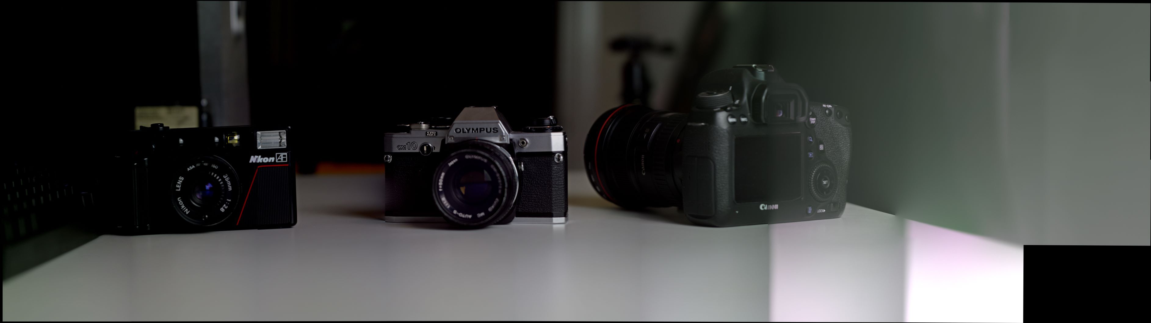
The stitched image is 34640x9743 pixels, which is equal to 337.5 megapixels. When MS ICE attempts to stitch the images together, it tries to match the brightness of each individual image to those which surround it. In a ‘normal’ panorama this makes perfect sense, however as some of these images have a dark side due to the body obstructing the sensor, this causes some strange exposure issues for these frames. One way to fix this issue is to take more images which overlap each other. This would ensure that there is always at least one frame which shows the un-obstructed view. MS ICE has also tried to level the exposure across the overal stitched image, which has caused the left hand side to become much darker than the original individual frames.
Test 3: Nikon 1 J2
A third test was done using many more individual images, covering a larger area of the lens. This resulted in the below image preview in MS ICE pre-stitching. The darker corners (vignetting) are clearly seen, as well as the pink shift due to the Nikon 1 J2’s sensor covering.
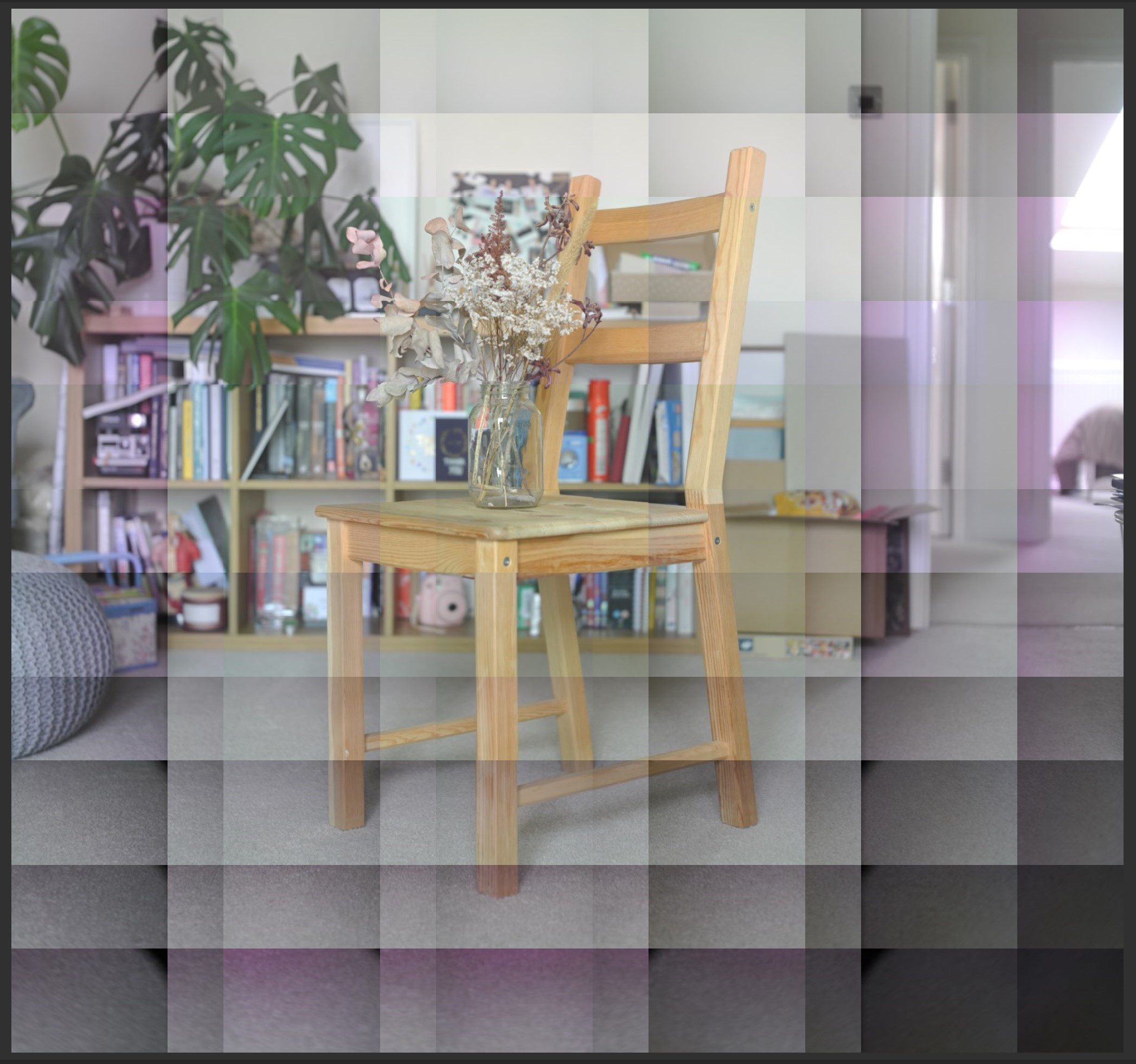
When MS ICE stitches the images, it attempts to correct for these issue and the result is an overcompensation for both the dark corners and the pink shift - resulting in the corners becoming overexposed with a green tint.
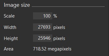
Below is the resolution of this test image - over 700mp! I am still trying to find a way to upload these in full resolution for easy viewing.
Test 4: Raspberry Pi HQ Camera
In early 2020 the Raspberry Pi Foundation released the Pi HQ Camera. It features a sensor which is bigger and higher resolution than previous Pi cameras, and it is designed for use with C or CS-mount lenses (which are commonly used in things like CCTV cameras). This camera is much smaller than those used in previous tests, with an even higher pixel density. It is also directly controllable with the Pi which is already controlling the motion system. This means we can try stitching images on the Pi using NumPy and OpenCV for a complete psudo large format camera! The below image shows the Pi HQ camera mounted to the motion system.
Initial testing showed that although the image stitching can be done on the Pi 4, the overall resolution possible is limited by the available RAM. This means that images of only around 500 megapixels can be created. One of the images stitched using this NumPy/OpenCV method on the Pi is shown below. Although the lens aperture and camera ISO, shutter speed and white balance are supposedly fixed, there are clear inconsistencies between the individual images. Some of these can be fixed by converting the image to greyscale, but the individual images are still noticeable. Using overlapping images, proper image stitching is possible with OpenCV but I have not yet tried this approach.
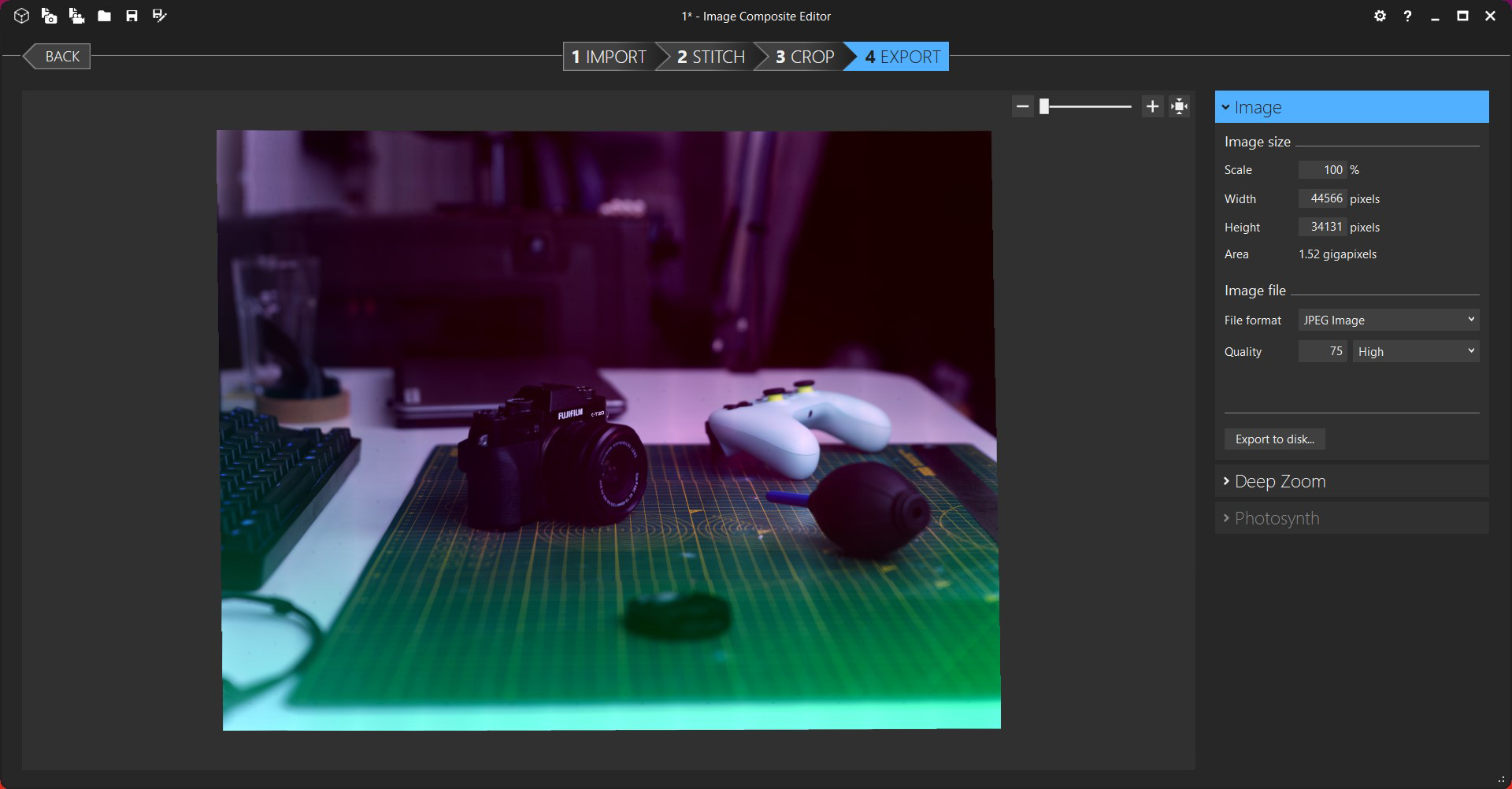
I have done another test using Microsoft Image Composite Editor, which does a good job at blending the image together (some faint lines and miss-matched edges are visible), and can stitch images at over 1,000 megapixels. This equates to a 10x10 grid of images using the Pi HQ camera, with an overlap of around 10%. A reduced resolution image is shown below, along with a cropped region.
See below for a full-resolution view.
Test 5: Raspberry Pi HQ Camera
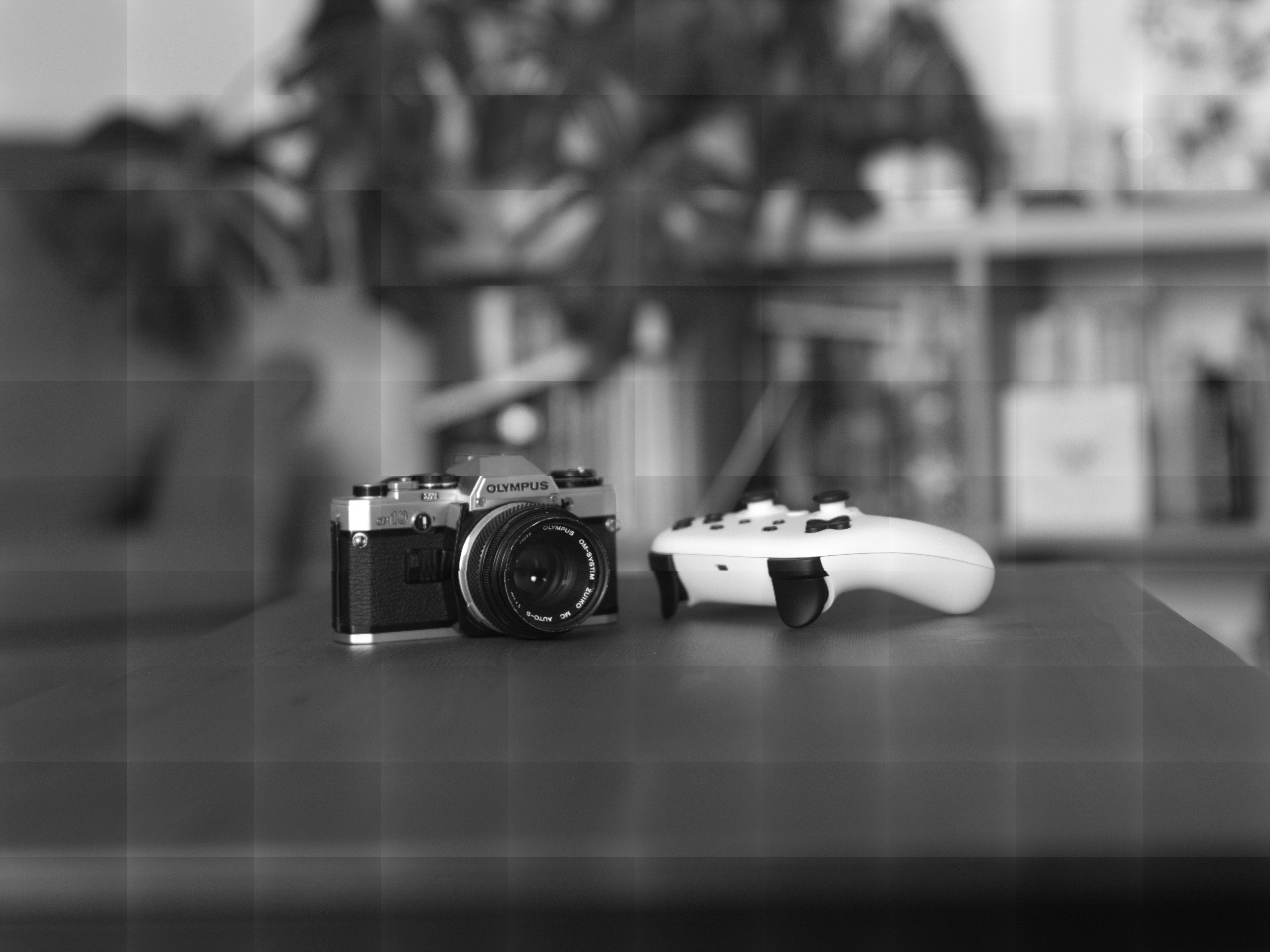
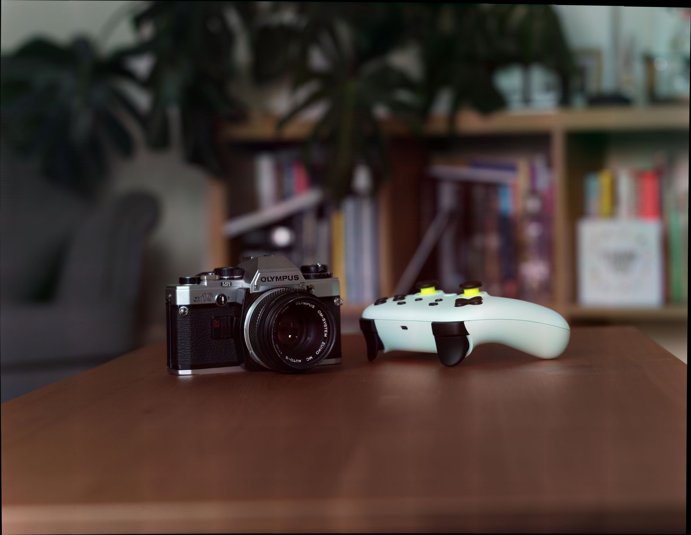
Below is are two screenshots from MS ICE. The first shows each of the individual images before stitching. The images are inverted as the Pi HQ Camera is mounted upside down in the motion system. It can be seen that the far edges have the same pink-shift that was happening when using the Nikon 1 J2. As digital sensors are designed to receive light from almost straight on, when they are used in applications like this where light is hitting them off-axis, colour shifts can happen.
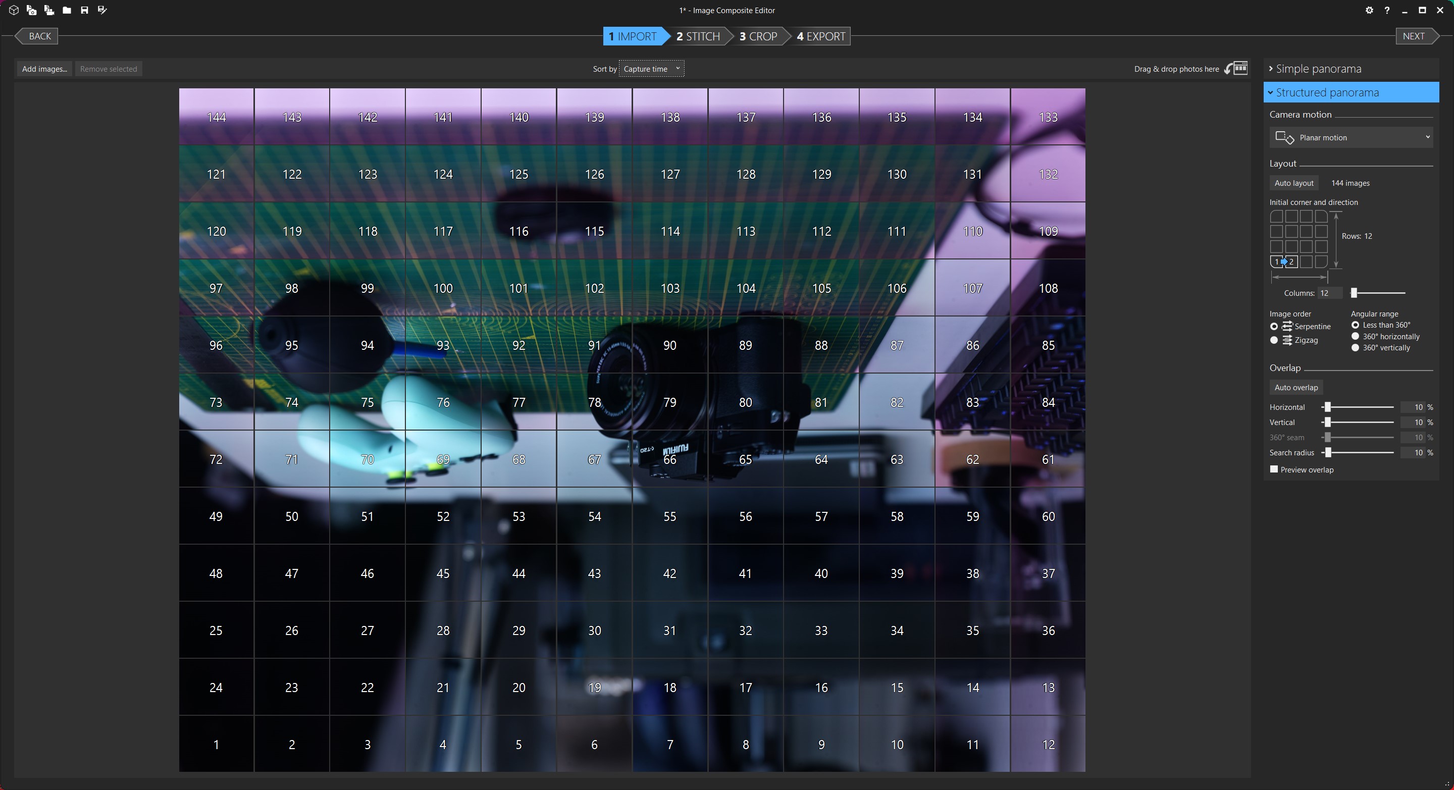
What makes this worse is the over-compensation MS ICE does when blending the image.
Below is the same image converted to black and white (and resized to around 12 megapixels from 1520 megapixels!)