Line Following Drone
This post shows the current state of a project to create a line following drone, with the goal of entering into the MAAXX Competition. As this project is still in progress, there are many things still to do and things here that will change.
Contents:
- System Overview
- Line Following Method
- Pitch/Roll Compensation
- Control Method
- Hardware and Body Design
System Overview
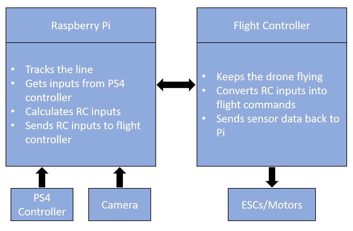
The project can be split into two main parts. The first part is to find and track the line and the second part is controlling the drone to follow the line.
Following a similar method to this post, a Raspberry Pi will be used to send flight commands (RC inputs) to a Betaflight based flight controller. The difference here is that instead of manual control using a PS4 controller, an onboard camera and OpenCV will be used to determine what inputs are needed to follow the line.
Line Following Method
OpenCV will be used to find and track a line from a camera onboard the drone. Initially a USB webcam was used, but I have now switched to the Pi Camera, mostly to save weight.
Using Python & OpenCV, the video stream from the connected camera is masked based on the desired colour of the line to be followed. Contours on this mask can then be found and the biggest one is assumed to be the line. A line of best fit can then be found based on this contour, and the gradient and intercepts with the edges of the frame can be determined. This means we now know where the line is within the frame and the direction it is heading. The below GIF shows a simple script which displays arrows depending on what side of the frame the line is on, and if it is facing to the left or right.
to do: add more detail and opencv method here with frame captures of each step
Pitch/Roll compensation
During flight, when a drone translates left/right/forward/backward it must either pitch or roll the entire body. This is a problem when trying to track a line as the camera view of the line will also shift. To combat this, a gimbal is ususally added to keep the camera straight when the drone is pitching/rolling. Instead of adding a gimbal, my current method takes the pitch and roll angles from the flight controller, and the field of view of the camera, and plots a point directly below the drone on the camera frame. As the drone pitches and rolls, this point will stay fixed below the drone, and allows the code to better understand where the drone is relative to the line on the ground. In theory this removes the need to add a gimbal to the camera.
This theory is shown in the below GIF (created in MATLAB), where the camera view moves but the blue dot (in the camera view) stays in the same location, directly below the drone.
I know there are problems with the accuracy of this method…but it seems to work well enough for me
Control Method
As mentioned in the system overview, this will closely follow the method used in my Controlling a Drone with a PS4 Controller post. For testing purposes, the drone will default to manual control using the PS4 controller and switch to autonomous flight when a button on the controller is pressed.
One of the main reasons for using a PS4 controller instead of a more standard RC controller for manual flight is that the Betaflight firmware can only accept one input method. This means switching from manual flight using PPM/SBUS etc. to autonomous flight using MSP during flight is not possible, so all flight controll must be done over MSP and switching modes must be done before the input to the flight controller (i.e. on the Pi).
Hardware / Body Design
(I might make a separate post for this section at some point)
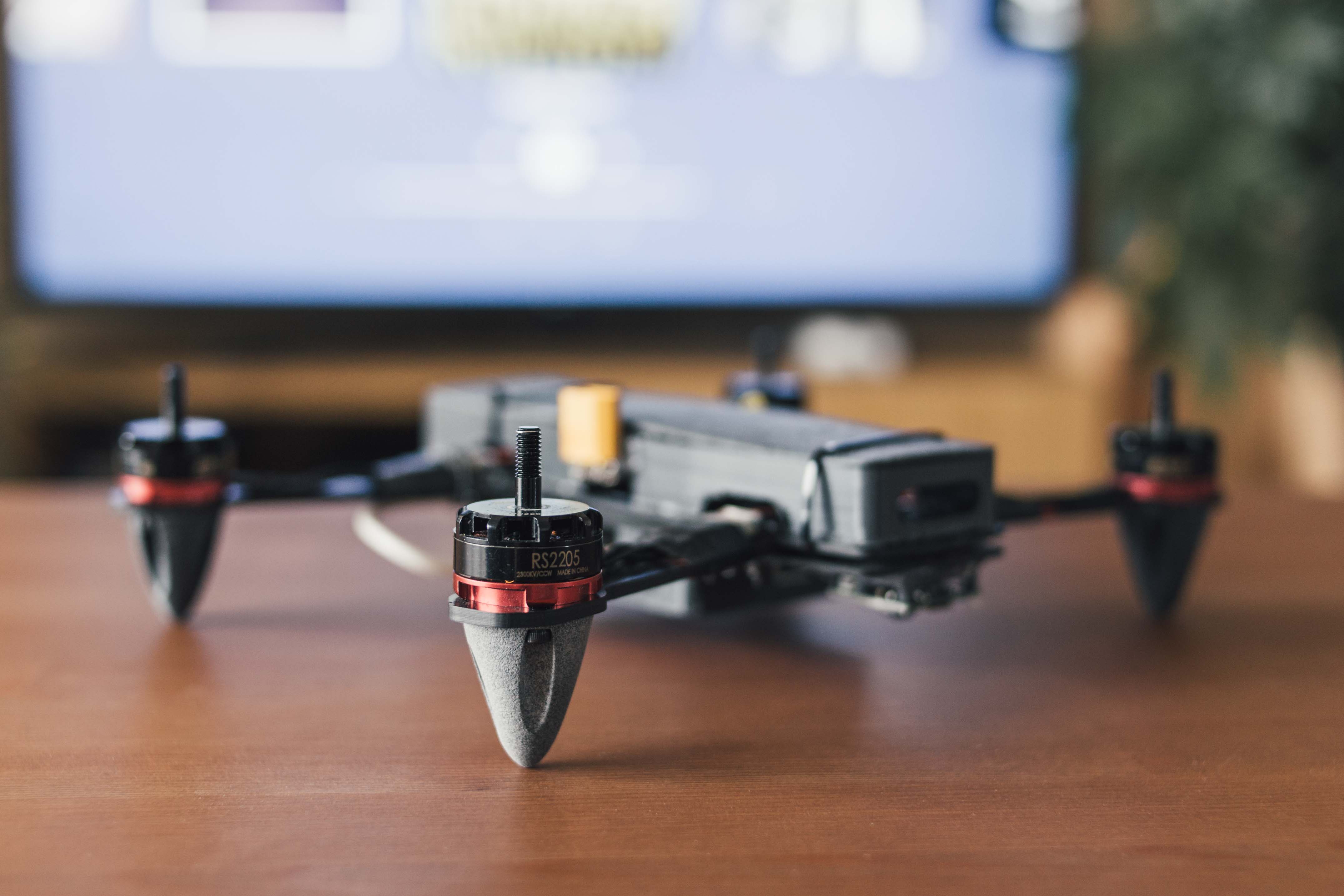
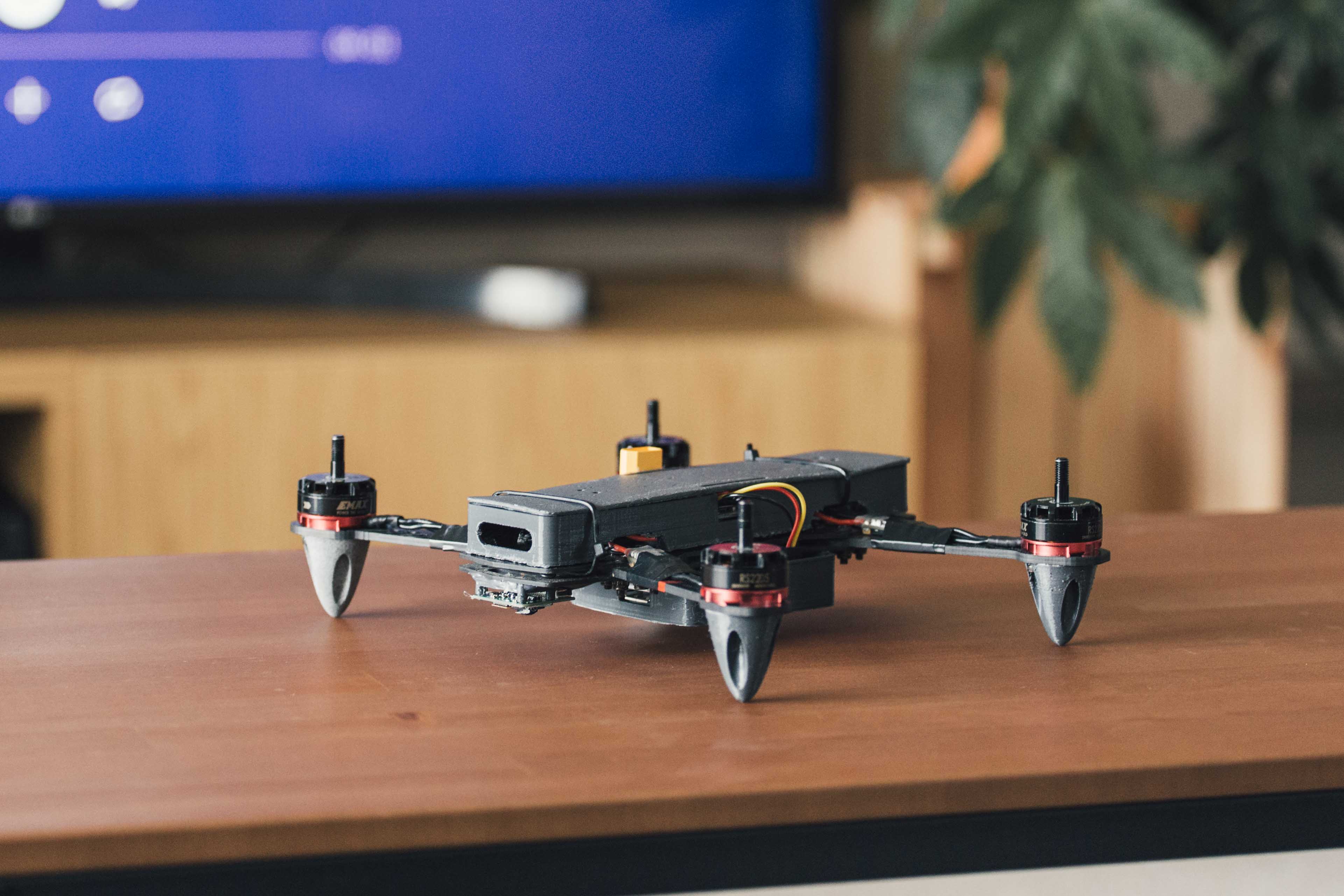
An existing carbon fibre body (ZMR 250) will be used as a base, and 3D printed parts to house the additional components will be added.
Some initial designs:
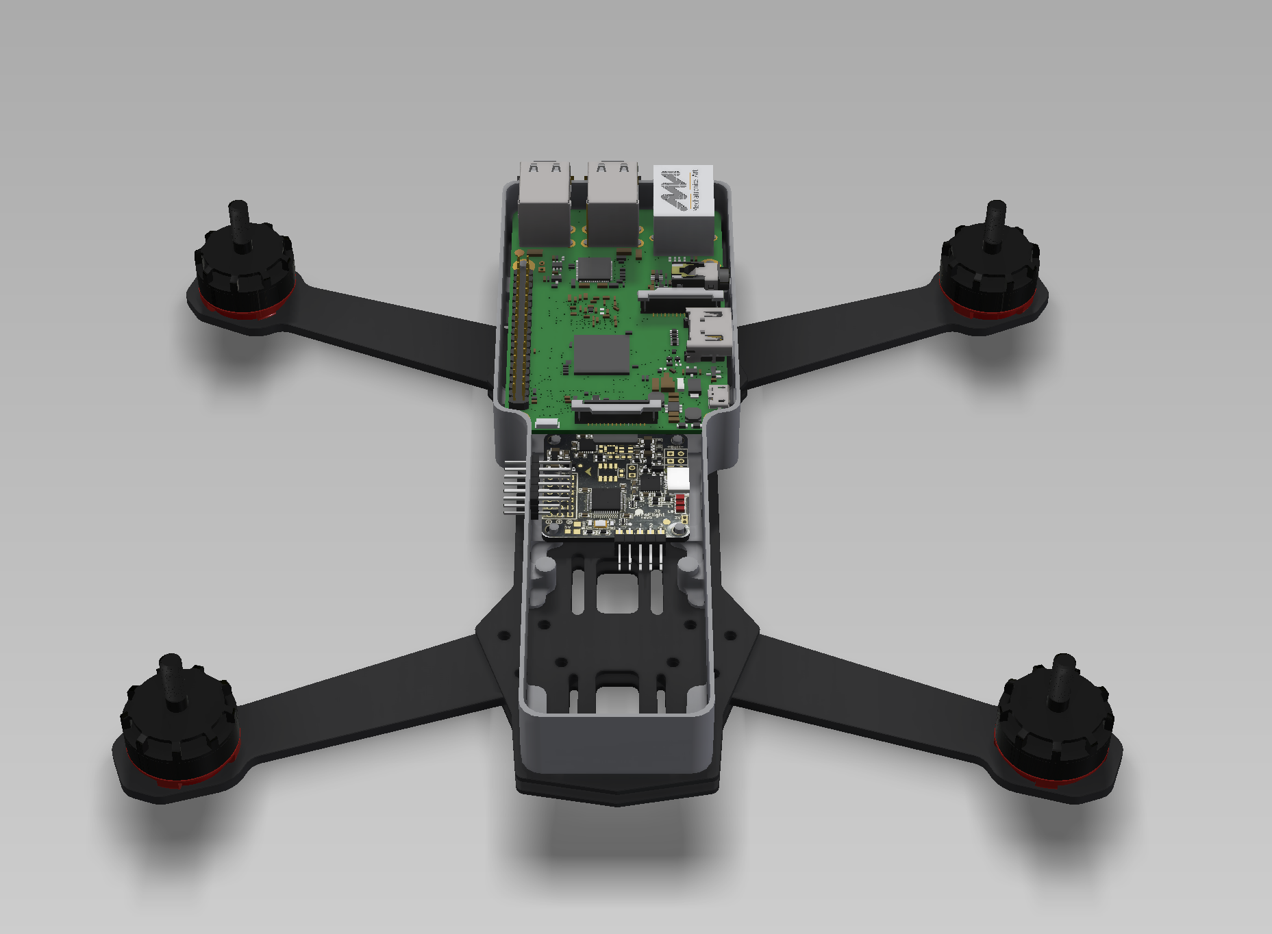
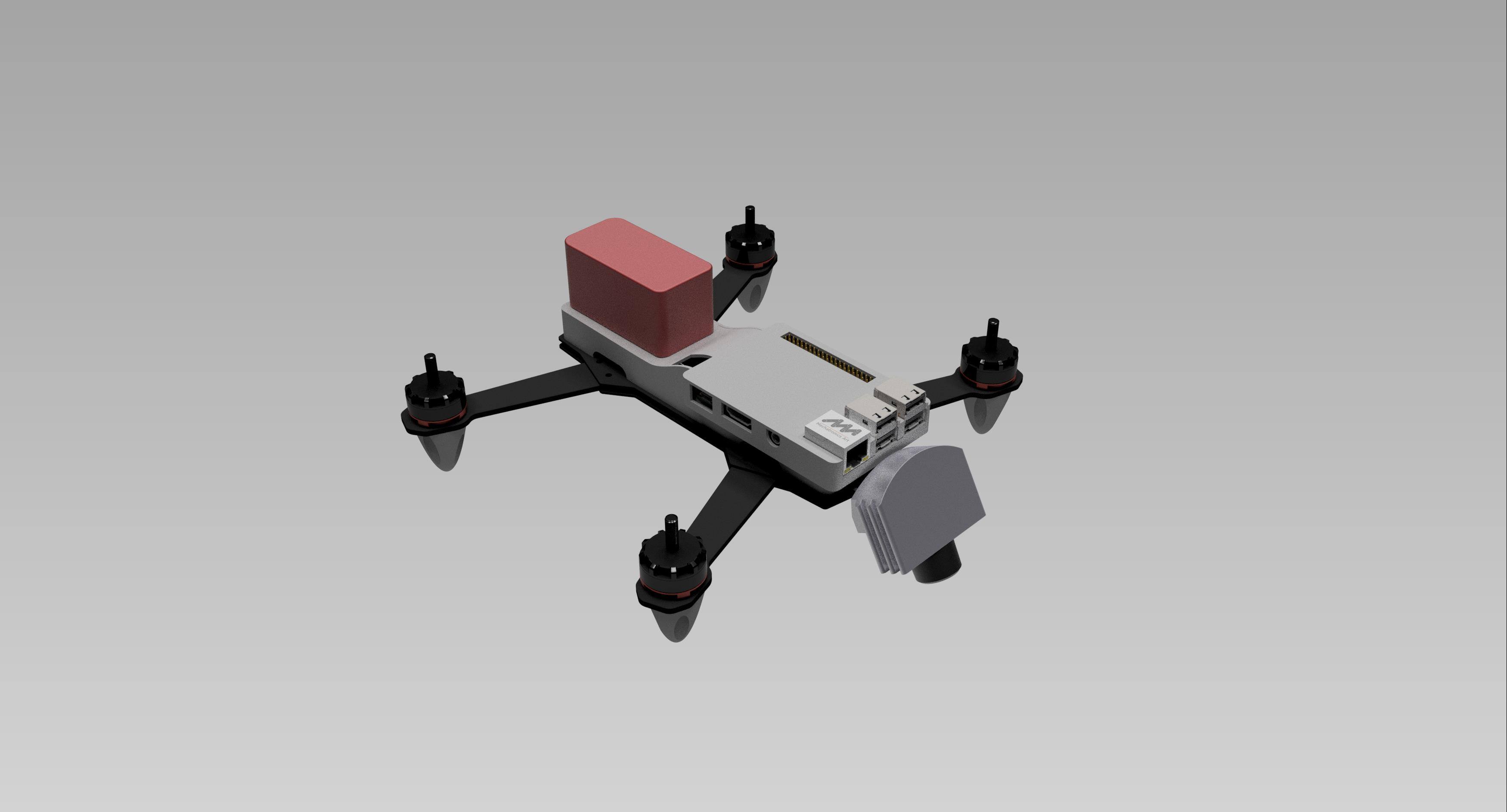
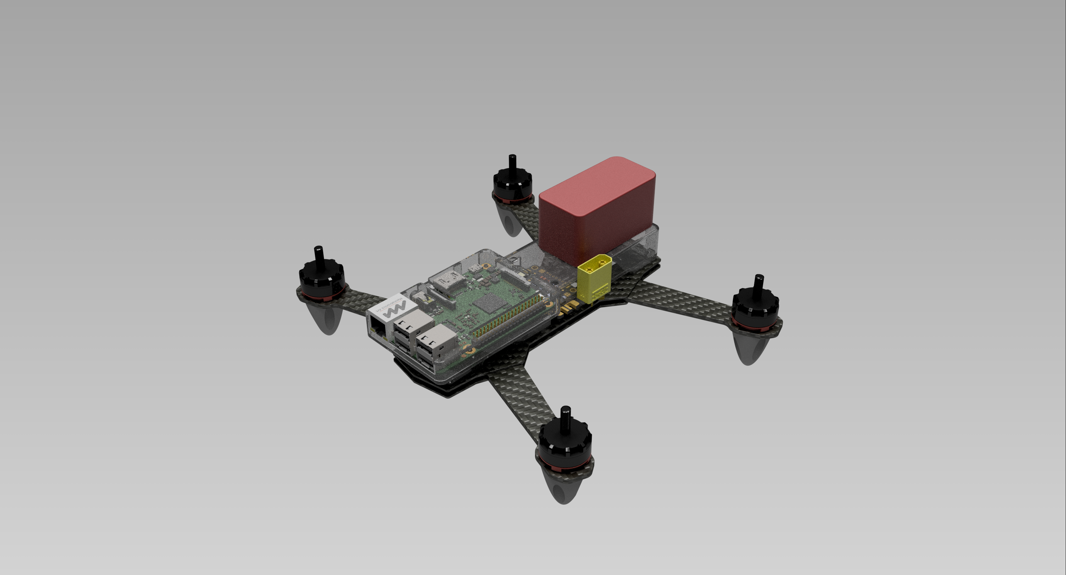
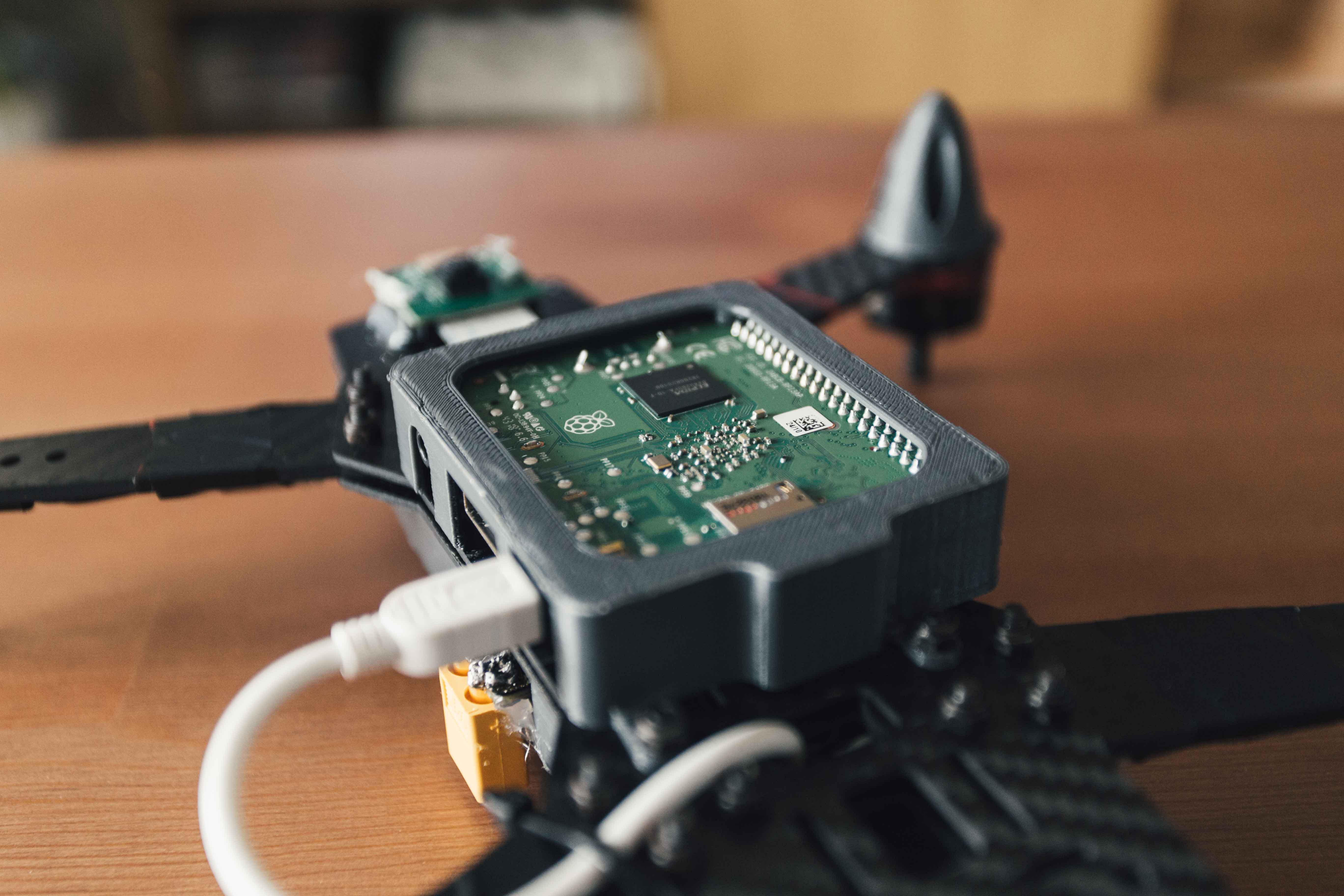
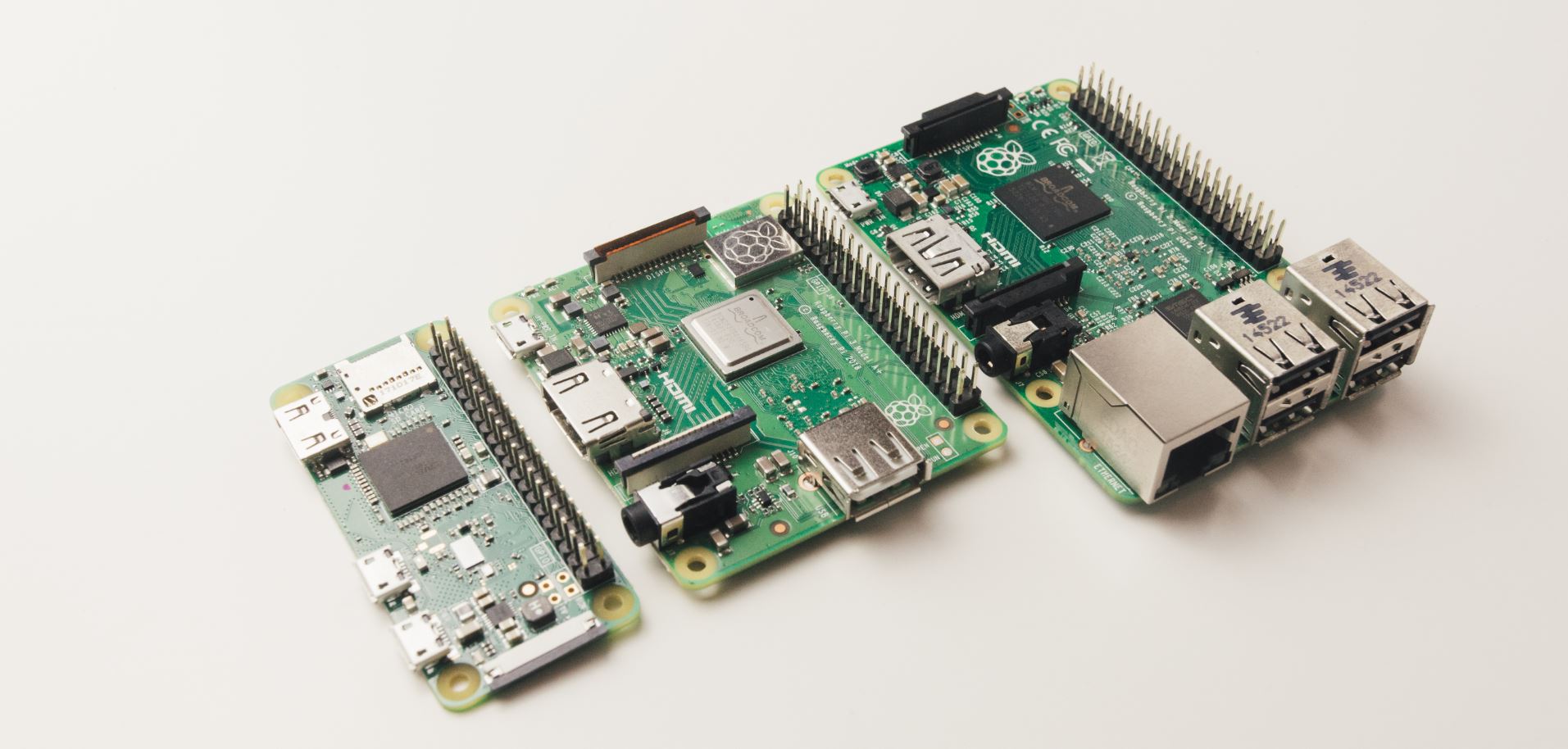
After some inital designs using the Raspberry Pi Model B, the current system switched to using the new Raspberry Pi 3 Model A (shown in the middle of the below image), which has a good balance of size/weight and performance. This allowed the Pi to be mounted below the drone frame, reducing the overall size and improving the centre of gravity. It also allowed easy mounting of the Pi Camera, and access to the GPIO for connection with the flight controller. The Pi is powdered using a microUSB cable, attached to a the 5V pad on the flight controller.
\