Designing a Drone in Fusion 360 using Generative Design & Modal Analysis
This post shows how generative design and modal analysis within Fusion 360 can be used to help design and develop a 3D printable drone body. For more specifics on Generative Design in Fusion 360, see my previous introduction post.
I am not an expert on Generative Design or Modal Analysis, these are just some initial experiments.
The following electronic components were used as part of the drone assembly:
| Component | Manufacturer |
|---|---|
| Flight Controller and ESC | HGLRC F428 F4 Stack |
| Battery | Turnigy 800mAh 3 Cell |
| Receiver | Turnigy TGY-iA6C |
| Motors | EMAX RS1306 4000kv (Version 1) x4 |
| Propellers | Gemfan 3035BN 4 Blade x4 |
Generative Design Setup
The above components were measured to determine their size and mounting dimensions. An initial preserve geometry could then be created in Fusion 360 as shown below. This preserve geometry will be used by the generative design process as a base to build the body. In this case the body is ‘upside down’ as this is the orientation that I want to 3D print it later, and the generative design process can only use the positive axis for the additive manufacturing method. It can be seen that there are four motor mount locations, a middle square which will house the battery, and a bottom plate where the flight controller stack will be mounted. Four holes pass through the battery slot to allow access to the flight controller bolts.
After the preserve geometry is done, obstacle geometry must be created. This tells the generative design algorithm where to avoid placing material. Initially, this geometry is placed where the battery, motors, flight controller, and bolt paths are located. As generative design has no way to simulate airflow, four large C-shaped bodies have also been created to allow space in the generated body for air to flow past.
Each motor is assumed to have around 3N of max thrust with the chosen propeller at 14.8V. A slightly higher load of 5N was applied to each motor mount, and fixed constraints were applied to the inside of the battery housing. In real life, no part of the drone is ‘fixed’ and instead the total force acts at the centre of gravity - but Fusion 360 will not allow a generative design to run without a fixed constraint somewhere, so this was the most reasonable solution as the battery is by far the heaviest component. This load case is vastly simplified over the actual loads which a drone will experience in flight, but currently it is very difficult/impossible to setup a generative design study with the complete dynamic load case of a drone in all possible flight conditions (at least within Fusion 360). The main force is the lift generated by each motor, and the other forces will be accounted for by a relatively large safety factor applied to the generative design case.
Generative Design Outcome Geometry
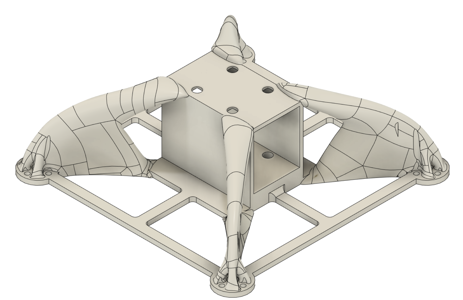
The generative design algorithm was set to generate an ‘unrestricted’ outcome, as well as three additive manufacturing outcomes (one for each positive co-ordinate axis) for more info on generative design outcomes, see the previous post linked at the top of this page. The additive manufacturing method outcomes are supposed to be generated in a way which makes manufacturing them easier. This sometimes works well, but in this case the unrestricted outcome (shown below) was already close to being 3D printable.
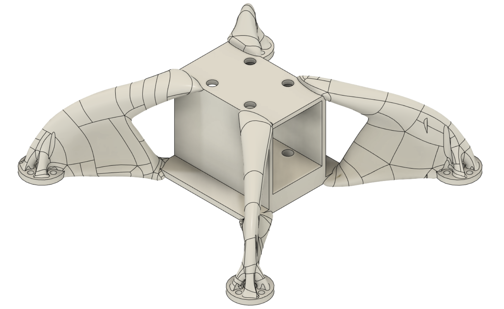
The only change which was made before 3D printing was to slice a small amount off of the base, to allow it to sit flat on the build plate without needing any support structure.
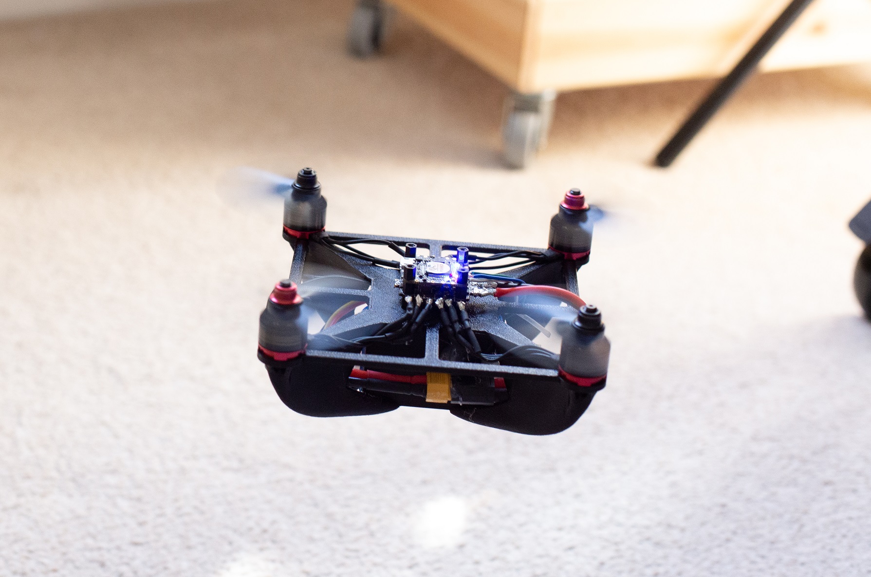
Initial Testing
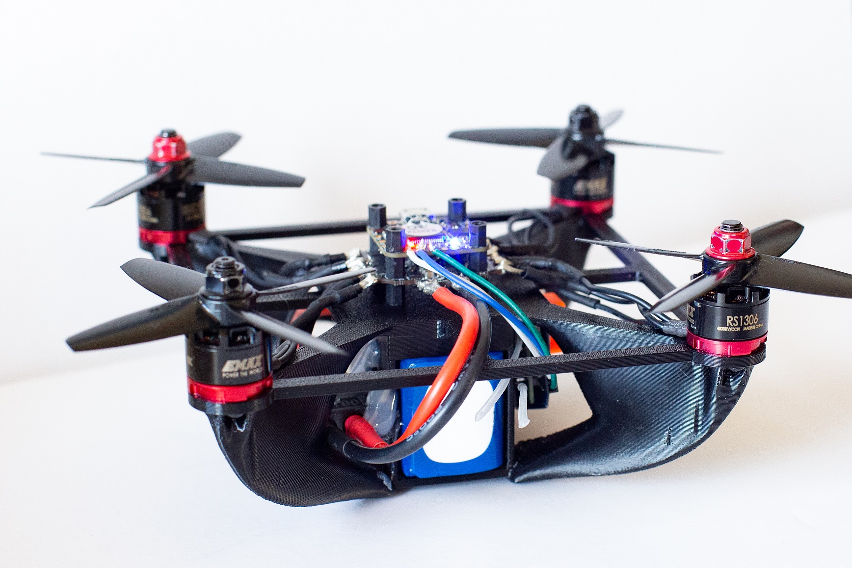
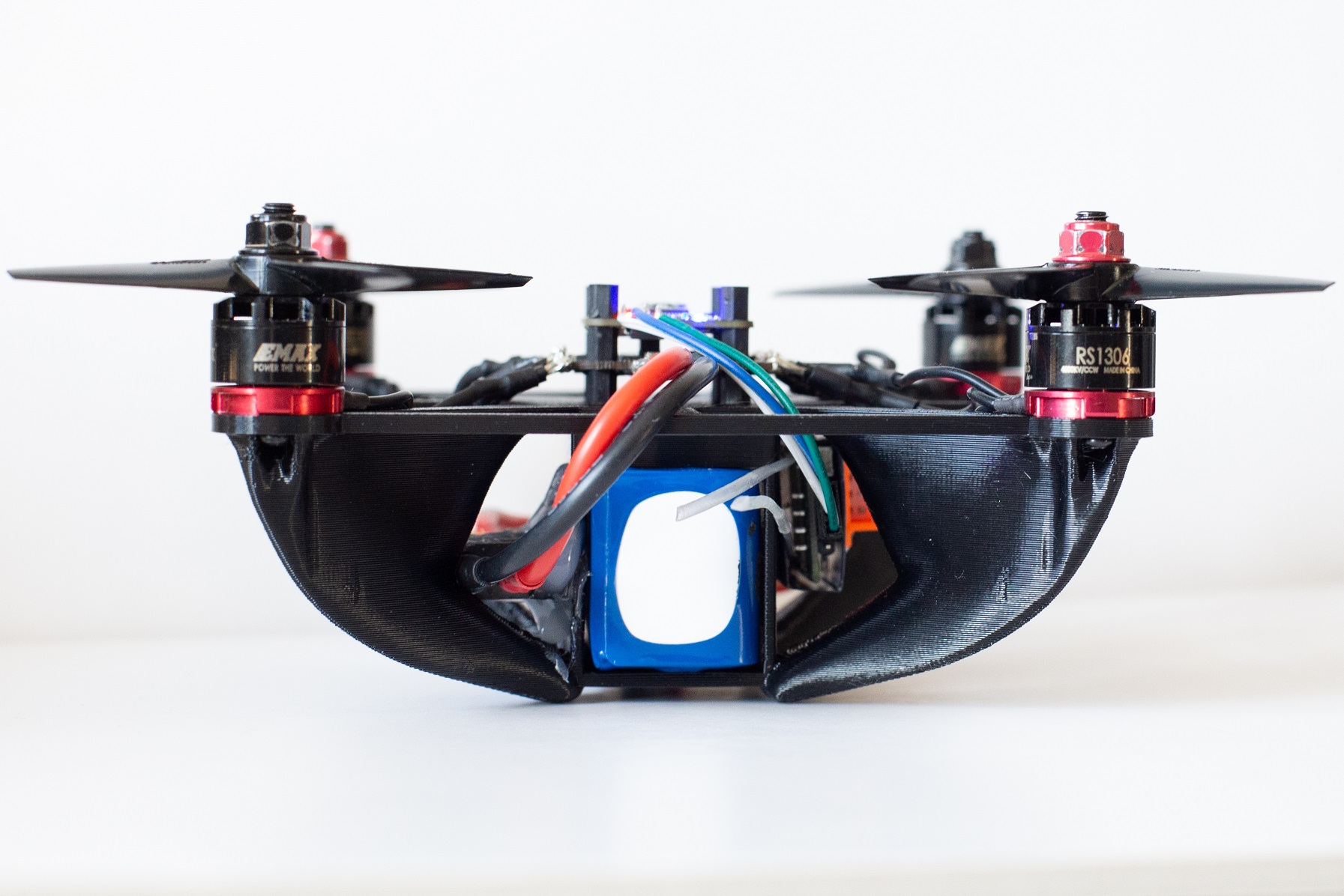
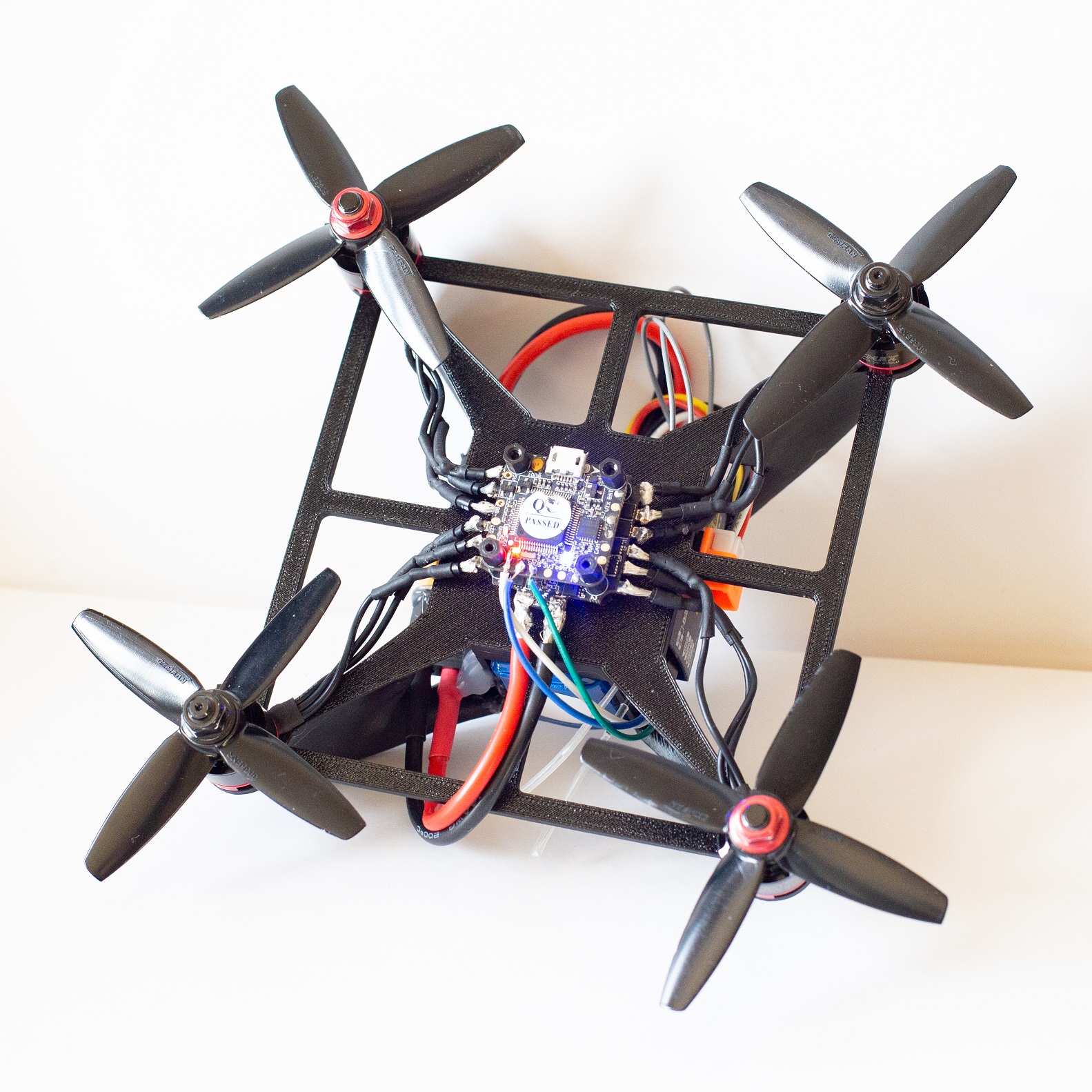
Once printed, the components were added to check the mounting dimensions and clearances were all correct.
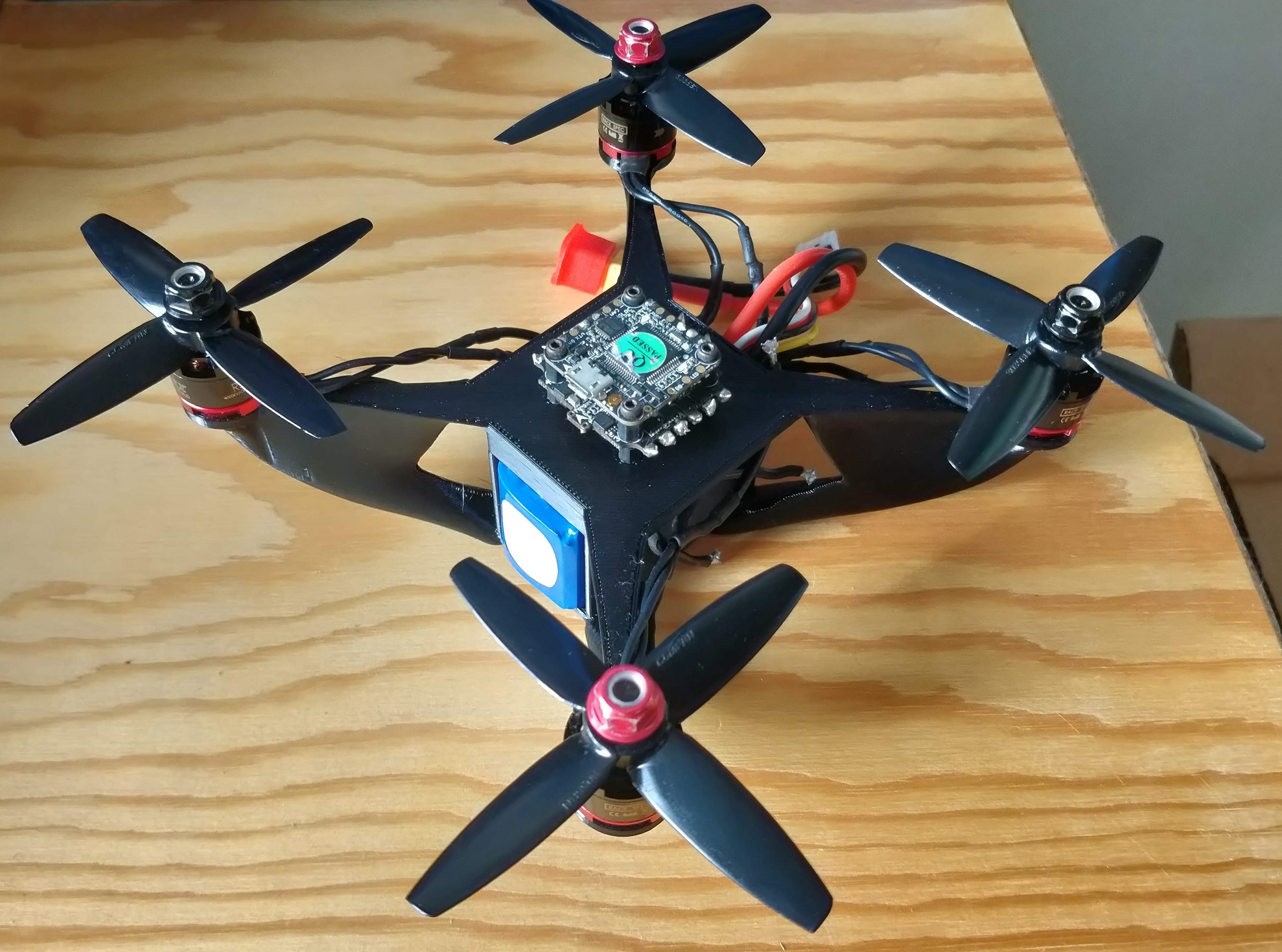
During the initial flight tests the drone was capable of controlled flight, but there were strong high frequency vibrations causing it to be unstable and the motors to heat up. The high frequency of the vibrations suggests that it was not an issue with the flight software configuration (i.e. Betaflight PIDs). Looking at the onboard blackbox data which was logged at 1KHz, strong oscillations can be seen in the gyro and accelerometer data, starting at around 10% throttle. Zooming in on the gyroscope data, regular oscillations can be seen at around 111Hz.
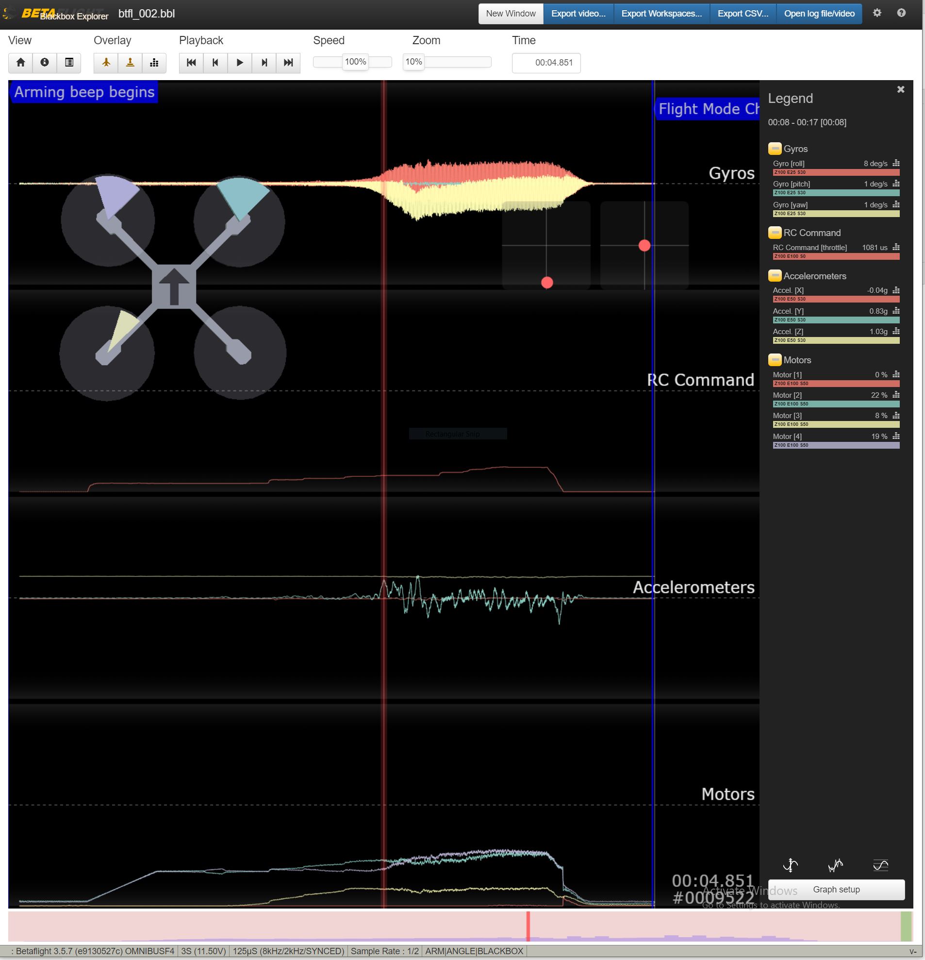
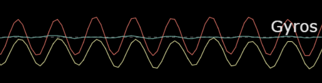
From the motor datasheet, there is no RPM given for 10% throttle, but extrapolating the data gives a theoretical RPM of 6665, which is equal to 111 revolutions per second - matching the oscillation frequency shown in the gyro data. This shows that the motors are reaching a speed which is causing the body to resonate.
The below video shows the harsh vibrations once the throttle is raised. In this case no propellers are mounted, but the vibration is the same with and without propellers.
As it is very difficult to see exactly how the body is vibrating at that frequency, a modal analysis was carried out using the CAD geometry in Fusion 360 in an attempt to understand the vibration and reduce it.
Modal Analysis
Modal analysis allows us to find various frequencies at which a structure will resonate, based on its mass and stiffness. Similarly to the generative design setup, modal analysis in Fusion 360 seems to require a fixed constraint on some part of the geometry. This will result in some modes being present in the analyis results which may not be exactly correct in real life - as instead of the body flexing, the whole drone would just rotate. The first mode is an example of this - it can be seen that the body is ‘flexing’ about the fixed constraint at the bottom. In real life this mode would not be likely as it would probably just rotate around the centre of mass instead of an unrealistic fixed point.
The first mode which seems plausible in real life instead of just a rotation about the fixed constraint is mode 4. This mode seems to not just rotate around the fixed constraint and it has a frequency of 120Hz - which is only just above the 111Hz frequency of vibrations found in the BlackBox data log, suggesting that it could be the same mode. The real part is not completely solid which would cause it to be slightly less stiff than the solid simulation. From the animation it looks like the arms are flexing mostly in the horizontal plane. This is not a suprise, as there is much less stiffness in this axis than the vertical direction.
Below is a table of the first 8 modes and their corresponding frequencies. To me, all apart from mode 4 and 7 do not seem to look as valid since they mostly just rotate about the unrealistic fixed constraint at the base of the body. As Mode 7 is quite a bit higher in frequency than Mode 4 I will ignore it for now.
| Mode | Frequency (Hz) |
|---|---|
| 1 | 89.48 |
| 2 | 108.1 |
| 3 | 119.2 |
| 4 | 120 |
| 5 | 145.1 |
| 6 | 379.2 |
| 7 | 501.4 |
| 8 | 517.3 |
Geometry Modification
In an attempt to increase the arm stiffness in the horizontal plane, additional geometry was added between each motor mount. This will of course add weight and drag, but it is mostly just a test to see if it works at reducing the vibrations.
Results from a modal analysis of the modified geometry show the first two modes stay the same, but they increase in frequency by 6% and 12% respectively. (Mode 1 comparison shown below).
Comparing the following modes directly is more challenging due to the added stiffening geometry. Mode 3 looks to be similar with all of the displacement acting in the same direction (but reversed), and the frequency has increased by 128%.
Mode 4 is the one which was suspected to be most plausible as the one causing the real vibrations experienced in the inital test flights. Initially it is not clear that the 4th Modes are the same, but each arm is seemingly moving/rotating in the same direction as before, suggesting it could be the same. If so, the frequency has been increased by 172% from 120Hz to 326.7Hz. I will not compare modes 5-8 here, but the animations are all at the bottom of this page for your viewing pleasure.
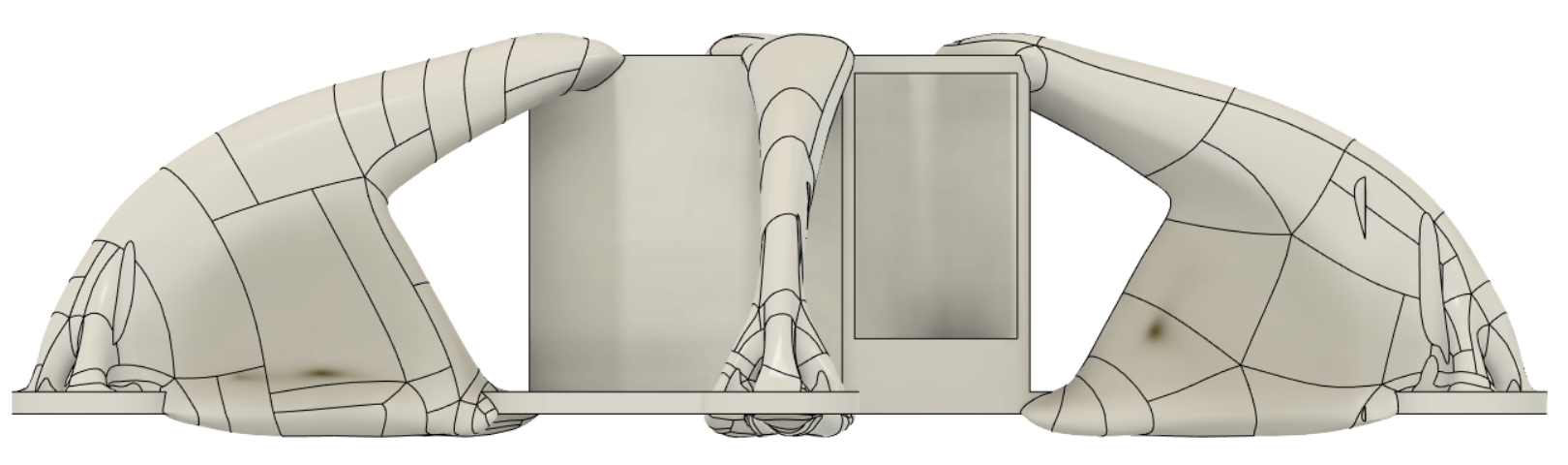
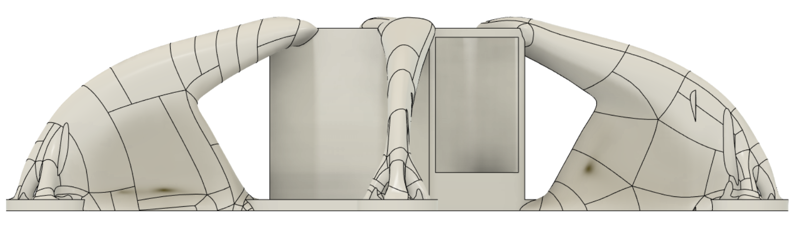
Once the modal analysis was complete, the modified geometry was 3D printed, and is shown alongside the original below.
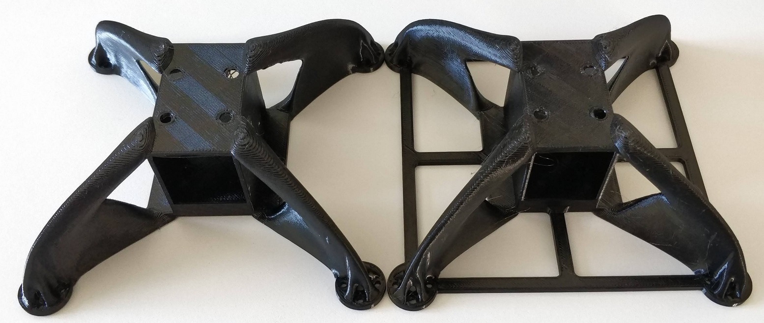
The same components were added, and a second test flight showed no sign of heavy vibration or resonance up to 50% throttle. No testing above 50% throttle has been done so far. The modified body weighs 54.69g, which is only 7g more than the original design which was 46.75g. The slight increase in mass (3% of the total 230g drone) and extra drag beneath the propellers is a small price to pay to remove the vibration present in the first flights.
Conclusion
Generative design in Fusion 360 is a useful tool, but the setup is still fairly limiting and it is almost impossible to generate a geometry with multiple objectives such as minimum mass and drag with maximum stiffness for a complex load case such as a drone. There are also currently some issues with the additive manufacturing method workflow which only gives an outcome in the three positive axes, this is a pain if the part is ideally printed in another direction. Rotating the part or co-ordinates is possible, but I found a bug in Fusion 360 when trying to do this so it is not currently recommended. Hopefully the bug is fixed soon and more control is added to the additive manufacturing method setup within generative design.
Modal Analysis can also be useful, but again due to difficulties accurately simualting FDM 3D printed parts, it is mostly good for just comparisons and rough ballpark figures.
Comparison of the First 8 Modes
Below is a table and some GIFs of the first 8 modes for both body geometries.
| Mode | Body 1 Frequency (Hz) | Body 2 Frequency (Hz) |
|---|---|---|
| 1 | 89.48 | 94.78 |
| 2 | 108.1 | 121.5 |
| 3 | 119.2 | 271.2 |
| 4 | 120 | 326.7 |
| 5 | 145.1 | 343.3 |
| 6 | 379.2 | 392.6 |
| 7 | 501.4 | 395.2 |
| 8 | 517.3 | 420.3 |