Generative Design in Fusion 360: Inital Study
This post looks at my initial testing of Fusion 360’s generative design process. Generative design is an iterative design process that uses artificial intelligence to generate the part geometry, based on a series of input parameters, such as the desired material and manufacturing process - this differs to topology optimisation, which essentially just cuts away regions of the part where the stress is low.
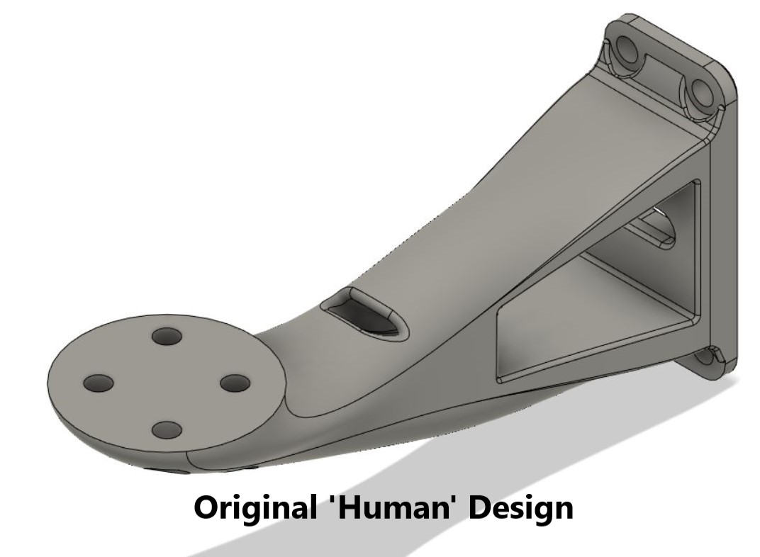
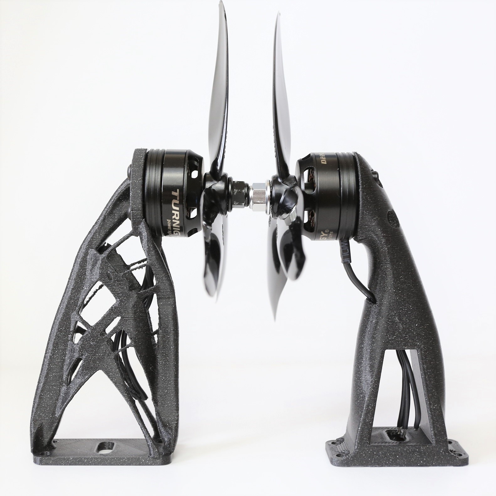
These tests will focus on a small 3D printable drone arm, which I initally designed for the SciRoc autonomous drone competition. The arm which I previously designed is shown below. On the left there is a mount for the motor and on the right there is a mount to the drone body. A hole was added for the motor cables, which will not be considered for the following generative design study.
Setup
To start the generative design process, only the essential geometry was created in Fusion 360. In this case, just the motor mount and the body mount. The distance between these mounts was also specified.
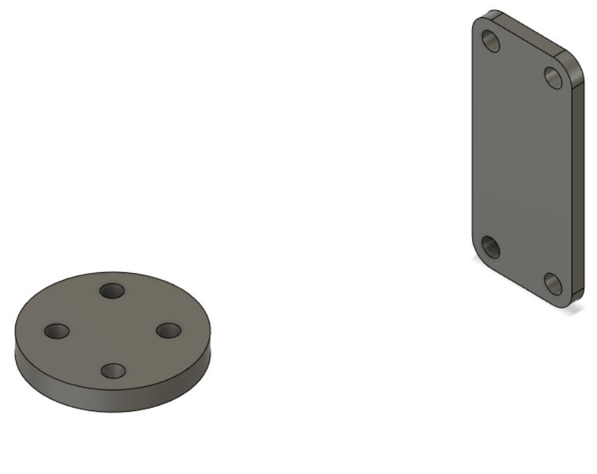
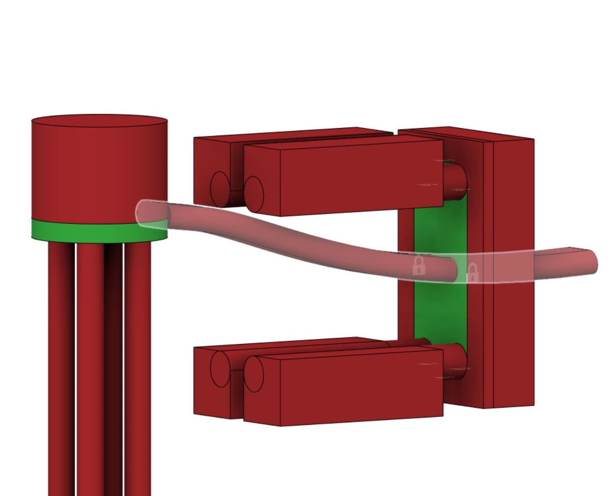
To ensure that the generateive design process does not add material in undesired locations, additional solid bodies were created in regions where access is needed - in this case for bolts or nearby components such as the motor and body.
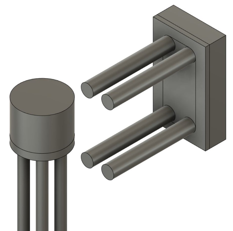
Next, the essential geometry is set to ‘preserve’ shown in green, and the other bodies are set to ‘obstacle’ in red. The structural loads and constraints can also be added. Here shown by the vertical motor force, and the fixed body mount.
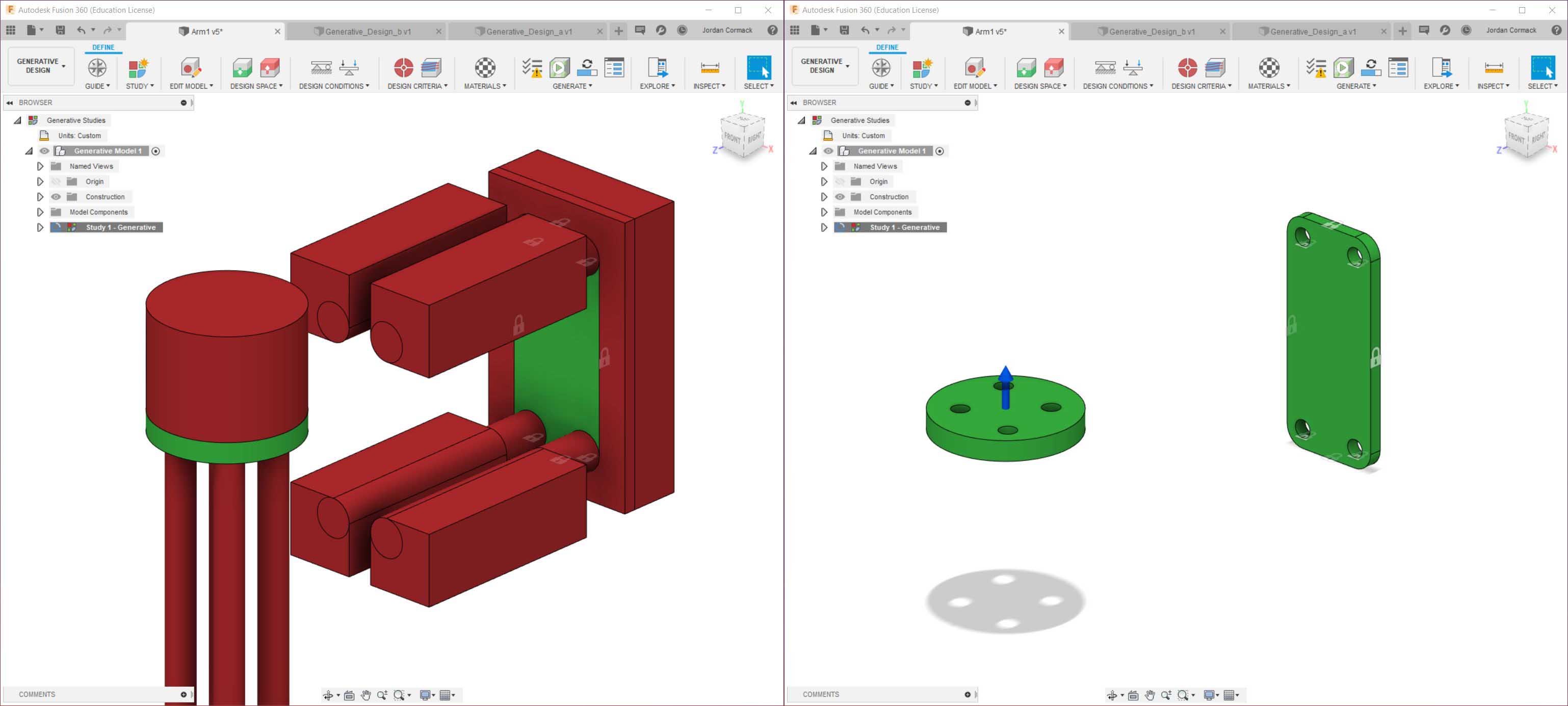
Since generative design in Fusion 360 takes into account the material and manufacturing process, these can also be specified. I have selected PA11 as the material and additive manufacturing and the process. Within the addditive manufacturing settings, a max overhang angle and mininimum wall thickness can also be set. The generative design objective was set to minimise stress, with the default safety factor left at 2.00 (a maximise stiffness objective is also available). An ‘unrestricted’ case was also run alongside the additive manufacturing one, removing the constraints for 3D printing. A previewer runs the first few design iterations, to allow you to check if the study has any obvious errors. It can be seen that the initial geometry is not too dissimilar to my ‘human designed’ arm.
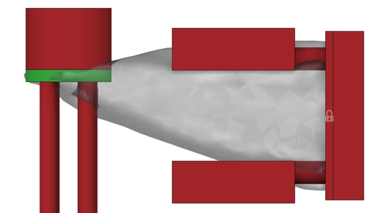
The generative design process can then be started. Instead of asking the user to specify the print orientation in the additive manufacturing setting, the generative design process gives three separate ‘outcomes’ - one for each of the XYZ axis. This means that the geometry will be designed in a way to hopefully produce a part which is not only optimised for the load, but also for manufacture. It can be seen that the first iteration generates essentially just a solid shape beween the specified bodies, but as the iterations increase, more complex geometry is forming.
Results
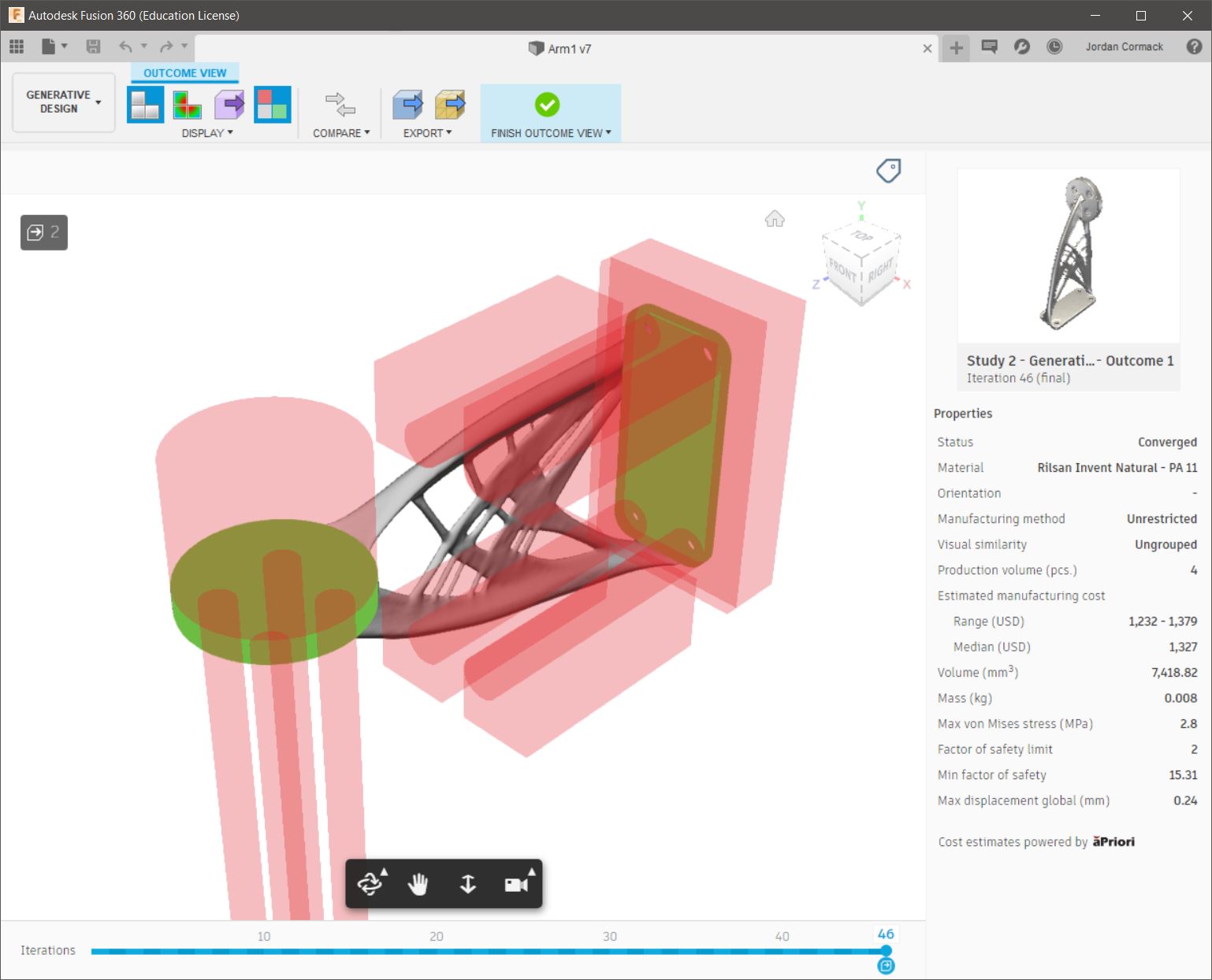
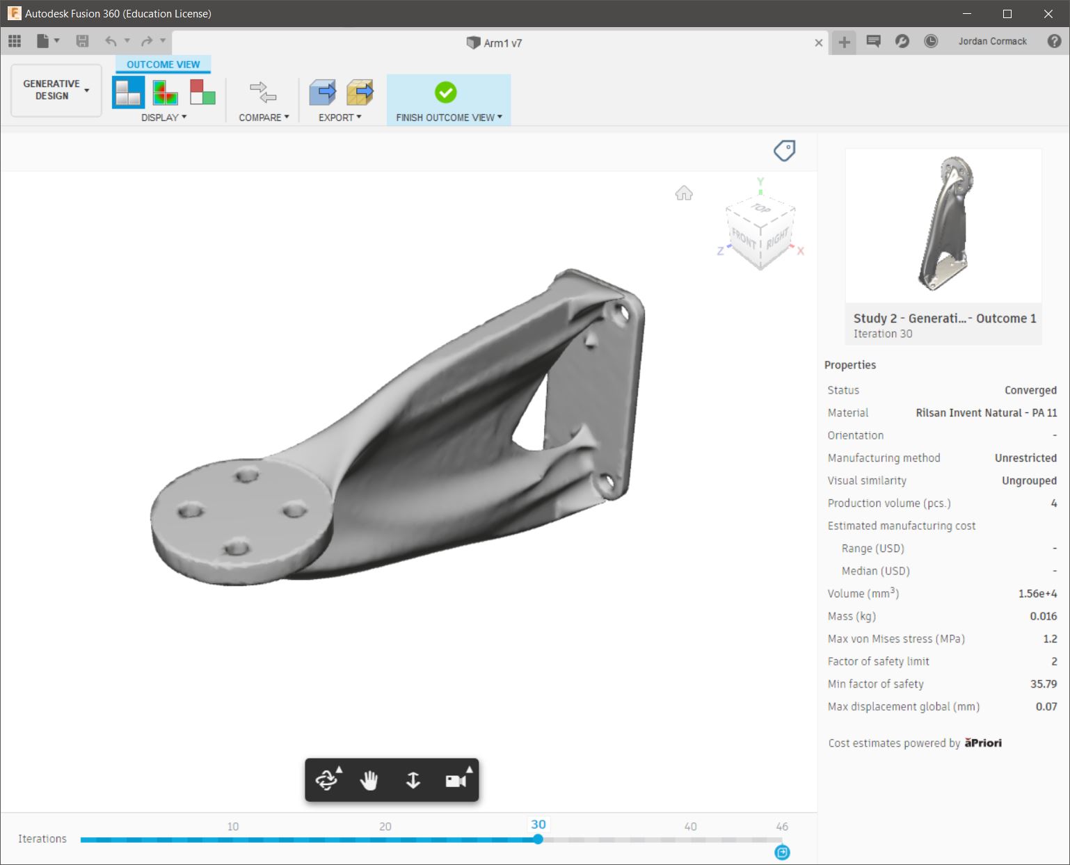
The final ‘converged’ geometry for the unrestricted case is shown below. As expected, the generative design process does exactly as it is told - minimising the object mass as far as possible whilst keeping the maximum stresses within those allowable for the specified material and safety factor.
Exporting this geometry as a .STL from Fusion 360 and importing it into PrusaSlicer reveals that this unrestricted case is definitely not ideal for 3D printing, with very thin regions which are not printable.
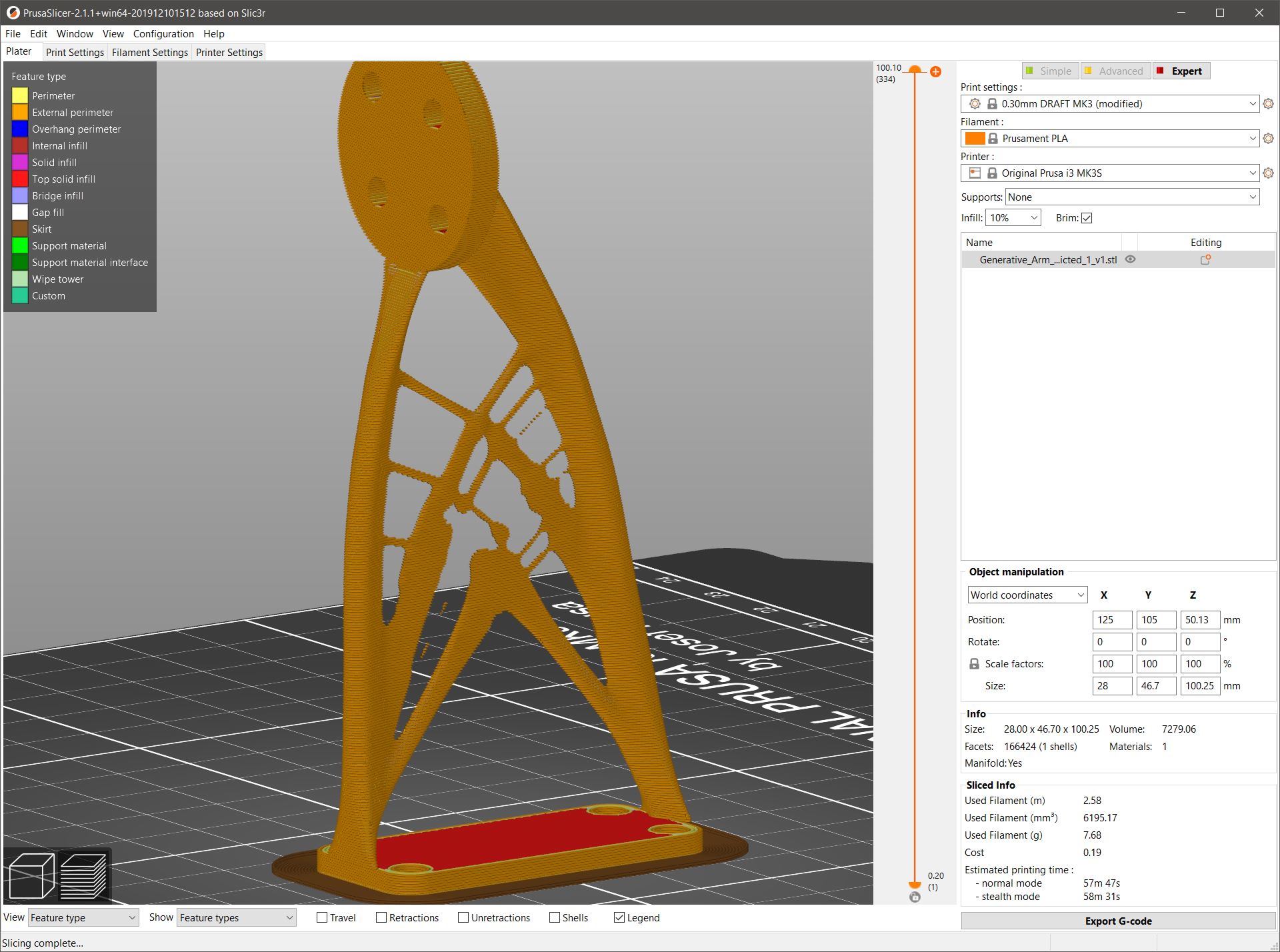
One way around this issue is to roll back a few iterations in the generative process. Going from the final iteration 46 to 30 shows a similar design, but just slightly less optimised. This geometry may not be as light as the final solution, but will be more easily manufactured, and the excess material will help in strengthening the part in any unplanned off-axis loading (e.g. knocks from the side or drops).
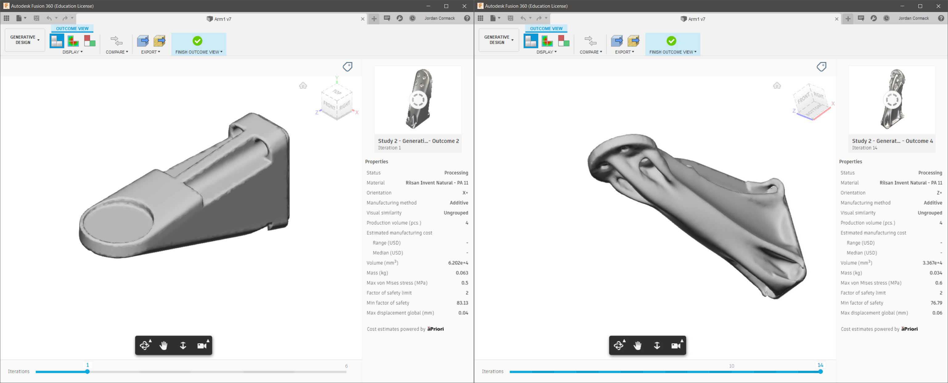
Looking at the additive manufacturing specific outcomes, the results are…interesting. As before, the generative design process has optimised for minimum mass, but in this case it has also attempted to produce a part which is 3D printable.
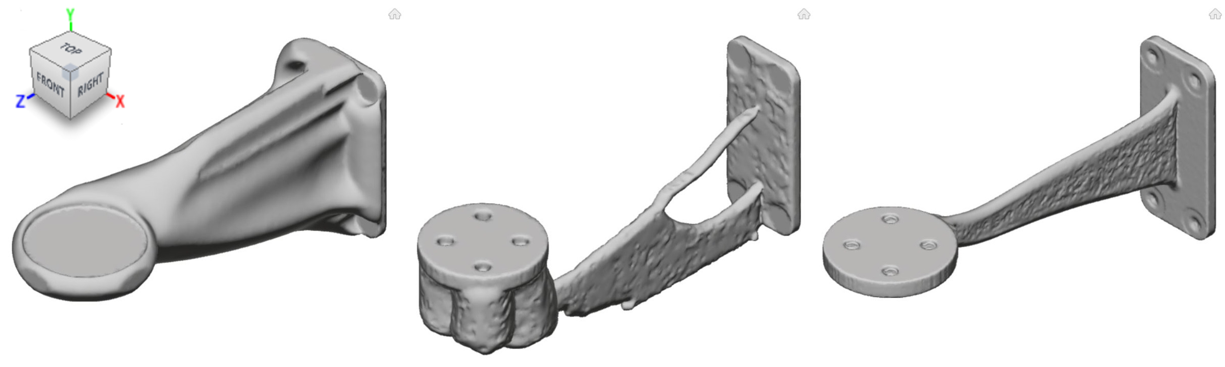
The first design is supposed to be optimised for printing in the X-axis, the second in the Y-axis and the third in the Z-axis. It can be seen that just changing the print orientation has a drastic effect on the final geometry, which is not dissimilar to an experienced human designing with 3D printing in mind. Although these parts have been optimised for printing in various directions, the final solutions is not always ideal. The X-axis optimised part is not symmetrical, which would cause the arm to twist as it is loaded. The Y-axis part would be very difficult to print without lots of support material. The Z-axis optimised part is probably the most ideal outcome, which coincidentally is the same direction the human design is intended to be printed. The Z-axis design is also very thin and weak in almost all directions aside from the load case specified, but this is expected. Adding more loads or increasing the safety factor could result in a part which is more ideal for real-world use, but as before rolling back a few iterations produces a more reasonable geometry.
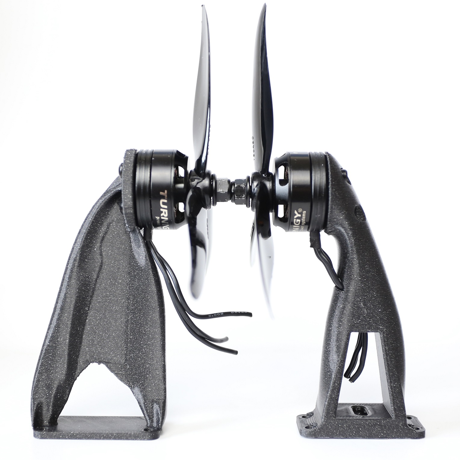
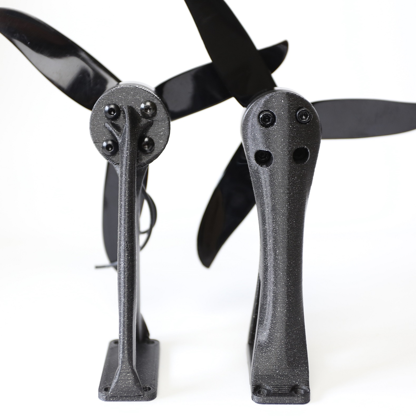
A rolled back iteration of one of the generatively designed parts was 3D printed in PLA to compare to the existing human designed part. Even the non-fully-optimised generative part saved over 25% of the mass over the human design and feels just as strong in the loading direction, although much more flex is present off-axis.
Conclusion
I think generative design in Fusion 360 is a very useful tool for easily optimising parts, but it is not yet a replacement for human design in a lot of cases. Specifying a high safety factor or rolling back from the final iteration provides a generatively designed part which is still robust to off-axis unplanned loading which is difficult to simulate fully.
Positives:
- Generative design allows complex designs to be created which may be much lighter or stiffer than those designed by humans.
- Cloud computing means even laptops can be used to create complex designs.
- Specifying the manufacturing process means the generated design is more manufacturable.
- Setting ‘obstacle’ regions for bolt access or nearby components is quick and easy.
- Generated designs can be saved as a part or mesh for further editing or simulation.
Negatives:
- It assumes a solid object, which is often not the case in 3D printing.
- Humans often design with many ‘objectives’ in mind. There is no way to optimise for low mass and high stiffness, or other factors such as low drag.
- The process can only focus on the loads you have specified - if the part is knocked or loaded off-axis, it could break easily.
- Some small seemingly irrelevant parts of geometry can still remain.
- Final geometry often needs a bit of post-processing to clean up edges or holes.
- Local machine power is not used to its full advantage.
- Saving/converting/exporting parts in Fusion 360 is SLOW. Sometimes I waited over 10 minutes just to save a .STL, which would take less than 1 second in Solidworks or Inventor.
- The final simulation views are a bit basic, further FEA may be necessary in some cases. In this example the X axis optimised geometry is not symmetrical which would case the arm to twist under load.
- Only limited materials are included by default
Update 1
Adding an additional ‘obstruction’ geometry through the middle of the part will ensure that there is space for the motor cables to run.
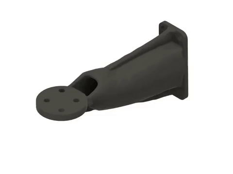
As before, the unrestricted outcome produces results which have very thin geometry in places. The unrestricted geometry was 3D printed and is shown below (left) next to the original human design (right).
As the thin sections of the unrestricted outcome were easily broken, an additive manufacturing outcome was selected, which resulted in much thicker walls. This geometry will likely be heavier, but will be more 3D printable and robust to forces other than the one specified in the generative design study.